CR2 - Installation
Installation at a minimal distance from another damper or from an adjacent supporting construction
Principle
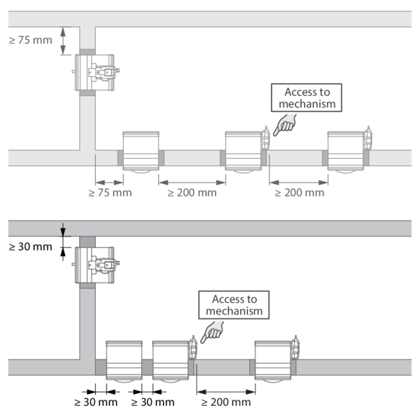
According to the European test standard EN 1366-2, a fire damper must be installed at a minimum distance of 75 mm from an adjacent supporting construction (wall/floor) and 200 mm from another damper, unless the solution was tested at a shorter distance. This range of Rf-t fire dampers has been successfully tested and can be installed in a vertical or horizontal supporting construction, at a distance below the minimum set by the standard.
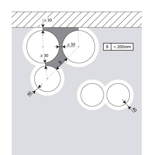
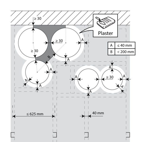
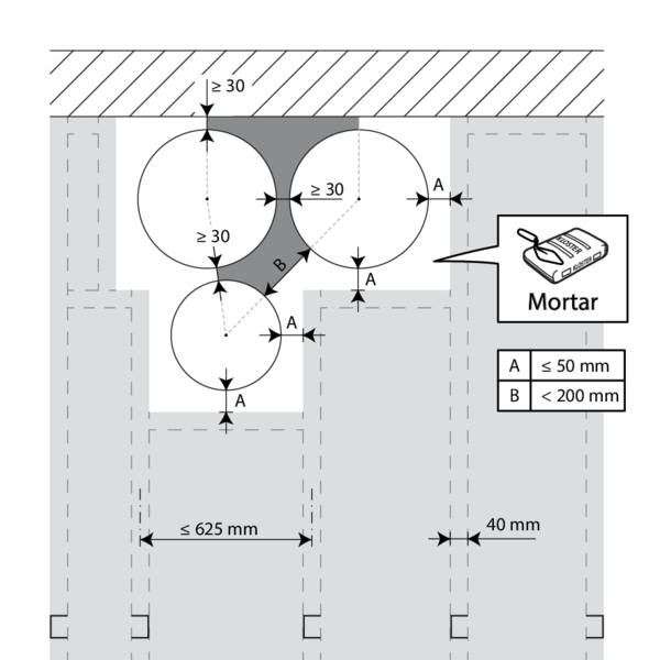
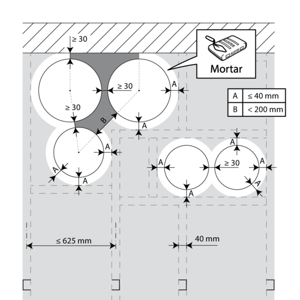
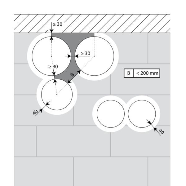
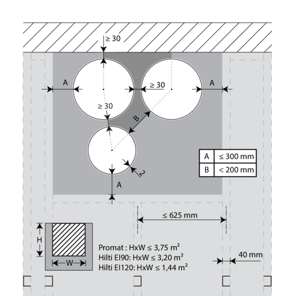
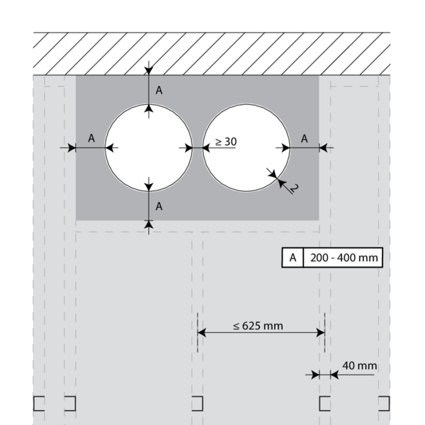
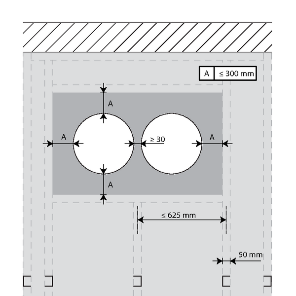
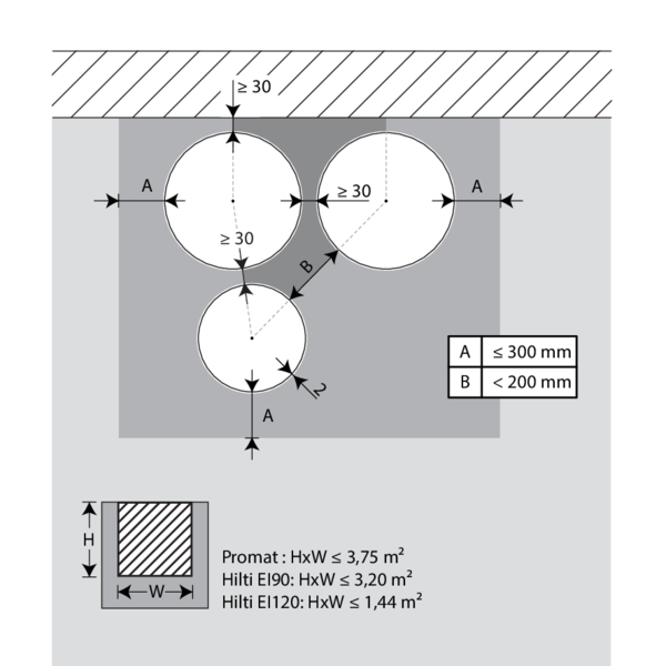
For circular dampers, the minimal distance is set to 30 mm.
According to the European test standard EN 1366-2, a fire damper must be installed at a minimum distance of 75 mm from an adjacent supporting construction (wall/floor) and 200 mm from another damper, unless the solution was tested at a shorter distance. This range of Rf-t fire dampers has been successfully tested and can be installed in a vertical or horizontal supporting construction, at a distance below the minimum set by the standard.
For circular dampers, the minimal distance is set to 30 mm.
Certified solution
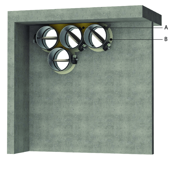
For the Rf-t fire dampers, the solution consists of the following elements: A: Universal sealing for minimal distance; B: Sealing compliant with existing classifications (Declaration of Performance).
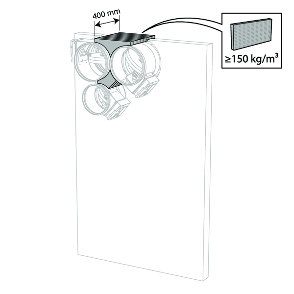
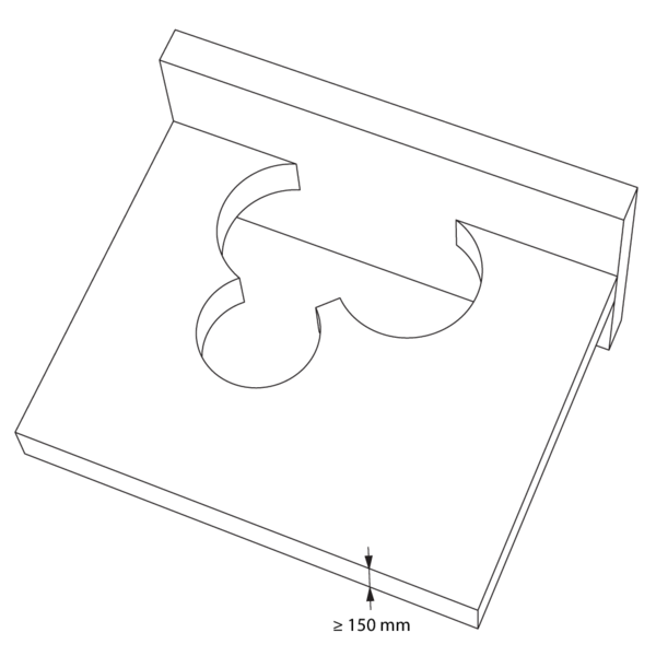
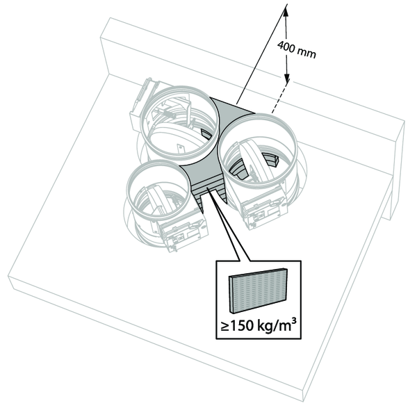
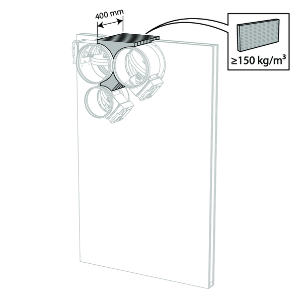
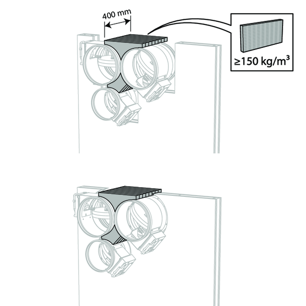
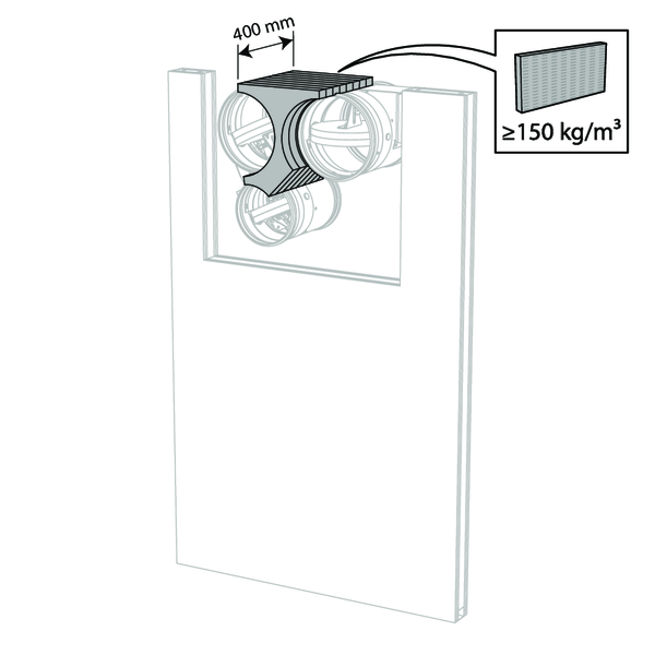
A. Sealing of the opening at the side with minimal distances between damper and wall/ceiling or another fire damper: rigid stone wool panels (150 kg/m³) are applied to a depth of min. 400 mm, of which 150 mm on the mechanism side of the wall. On the non-mechanism side of the wall, the stone wool panels must be at least flush with the wall.
The surface of this sealing is set between the axes (centres) of the dampers.
B. Sealing of the rest of the opening according to the existing classifications for the fire damper (Declaration of Performance).
This also applies to circular dampers that are mounted at a minimum distance from one another (30 to 200 mm) but at a distance greater than 75 mm from a wall/ceiling.
Detailed information for each wall/sealing combination can be found in the respective installation methods.
For the Rf-t fire dampers, the solution consists of the following elements: A: Universal sealing for minimal distance; B: Sealing compliant with existing classifications (Declaration of Performance).
A. Sealing of the opening at the side with minimal distances between damper and wall/ceiling or another fire damper: rigid stone wool panels (150 kg/m³) are applied to a depth of min. 400 mm, of which 150 mm on the mechanism side of the wall. On the non-mechanism side of the wall, the stone wool panels must be at least flush with the wall.
The surface of this sealing is set between the axes (centres) of the dampers.
B. Sealing of the rest of the opening according to the existing classifications for the fire damper (Declaration of Performance).
This also applies to circular dampers that are mounted at a minimum distance from one another (30 to 200 mm) but at a distance greater than 75 mm from a wall/ceiling.
Detailed information for each wall/sealing combination can be found in the respective installation methods.
Restrictions
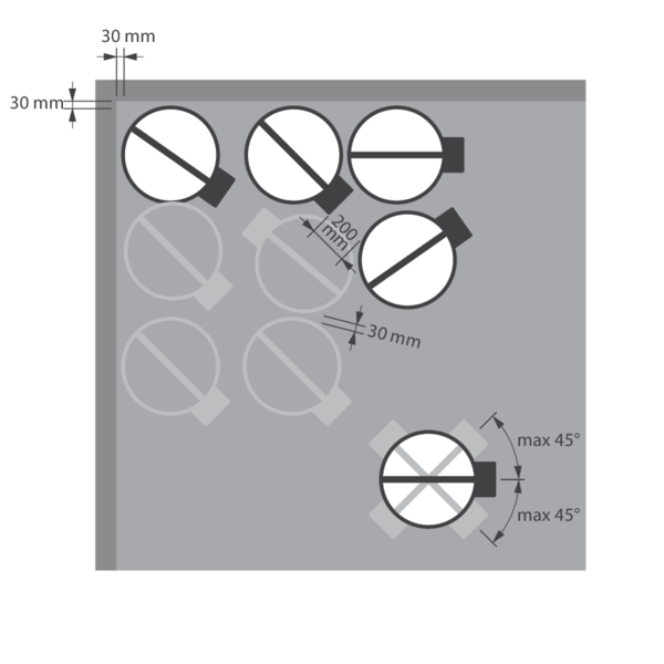
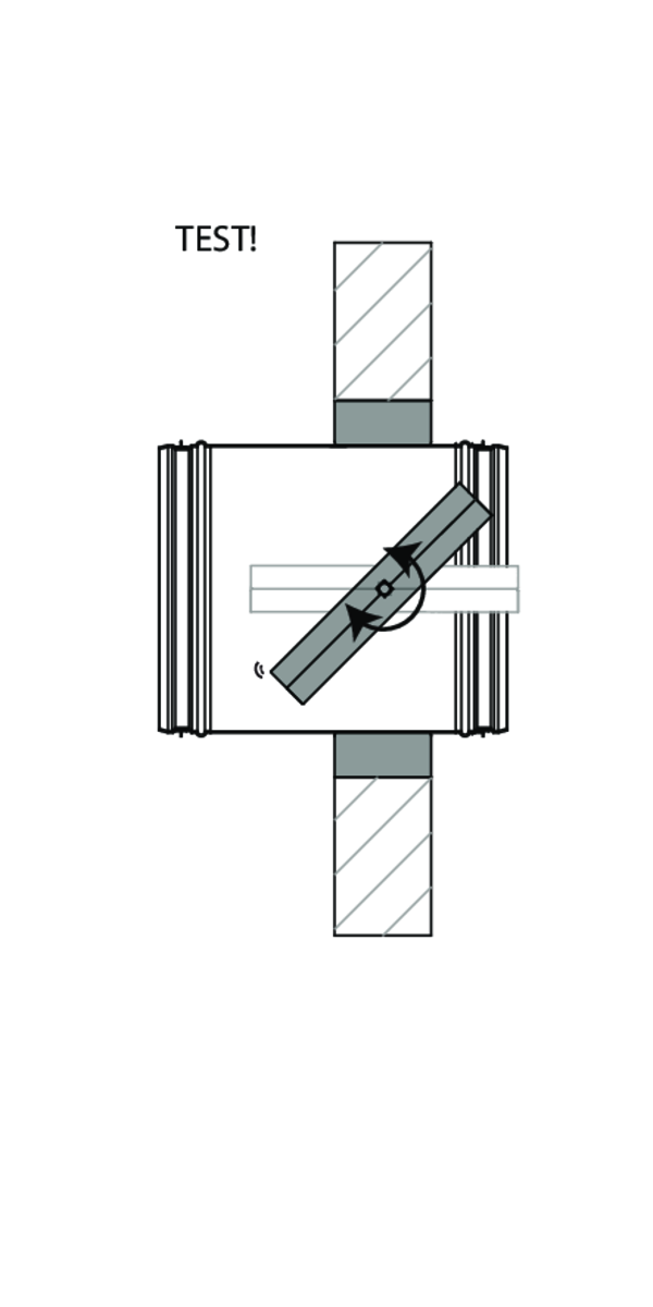
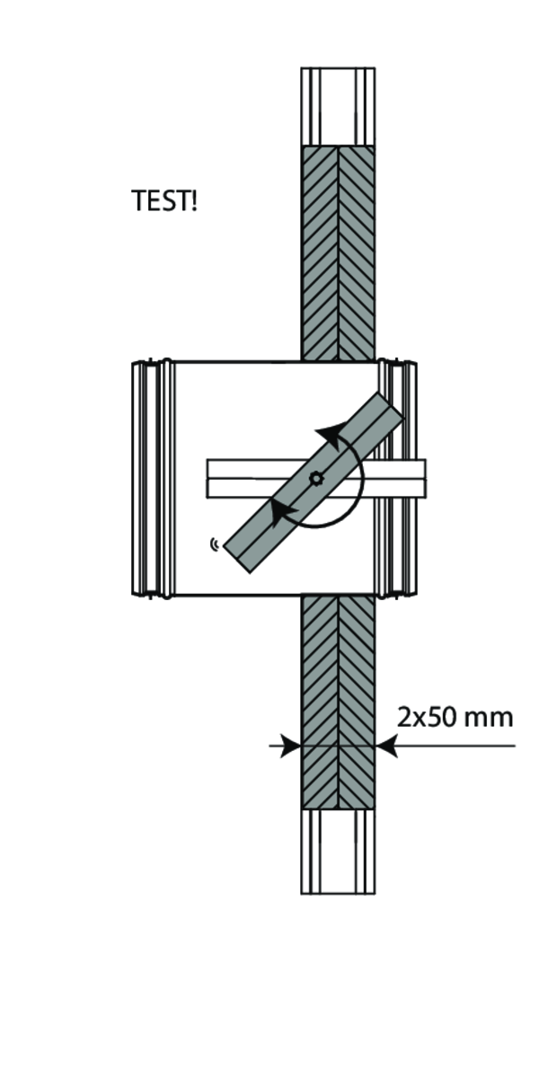
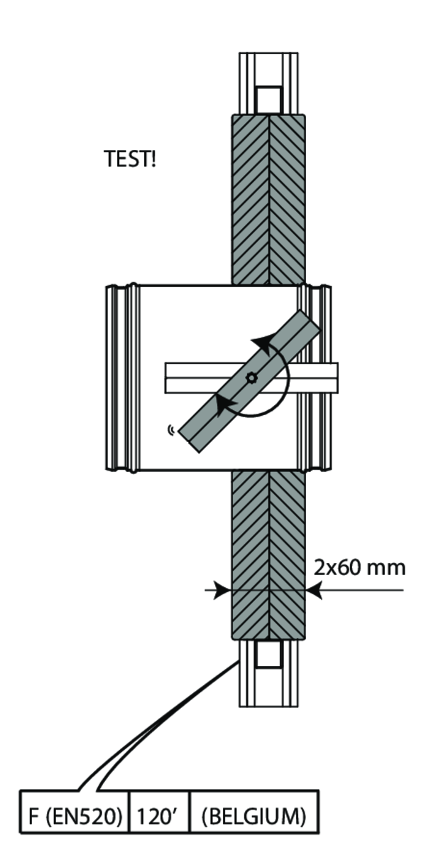
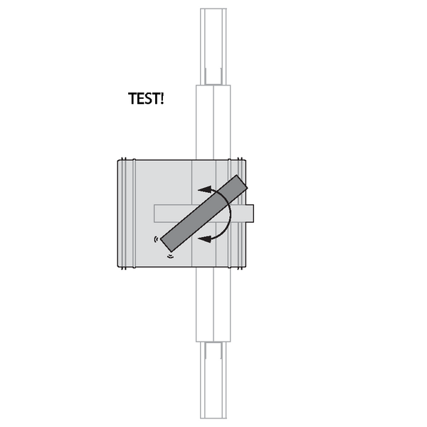
The orientation of the blade axis should be horizontal or oriented at a maximum of 45°.
A maximum of 3 circular dampers can be installed at a minimum distance from one another, both vertically and horizontally (with a maximum cluster of 4 dampers).
Note: when sealing the opening with panels of fire resistant stone wool, the maximum number of dampers also depends on the maximum “blank seal” allowed for the selected sealing material. Please refer to the manufacturer's instructions for this information.
Installation in rigid wall
The product was tested and approved in:
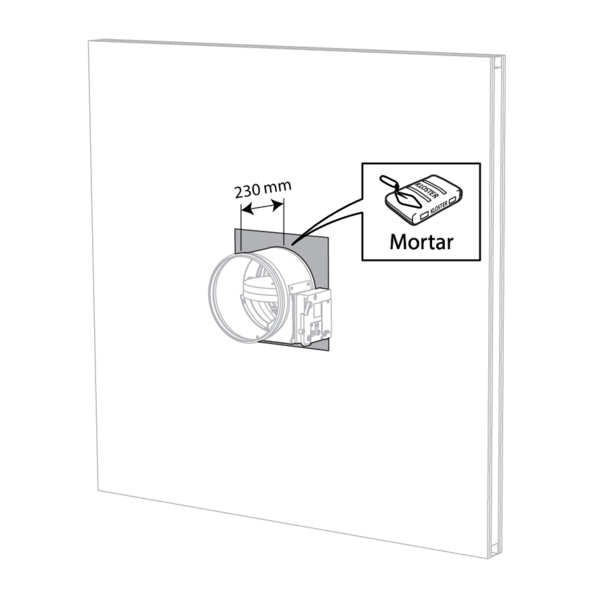
- Aerated concrete ≥ 100 mm | EI 120 (ve i o) S - (500 Pa) | Mortar / Gypsum plaster | Type of installation: built-in, 0-360°. Minimal distances authorised with axis till 45°. | Ø 200-630 mm
- Aerated concrete ≥ 100 mm | EI 90 (ve i o) S - (300 Pa) | Mortar / Gypsum plaster | Type of installation: built-in, 0-360°. Minimal distances authorised with axis till 45°. | Ø 200-630 mm
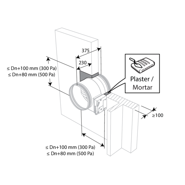
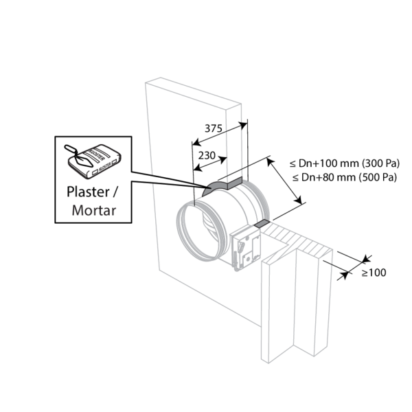
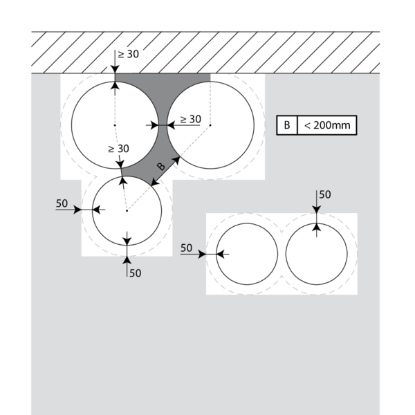
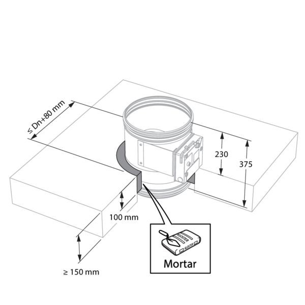
The dampers can be installed at a minimum distance (≥ 30 mm) from an adjacent wall or from another damper.
Make the necessary openings (≤ Dn + 100 mm) / (≤ Dn + 80 mm) in the wall.
Mount the dampers in the opening.
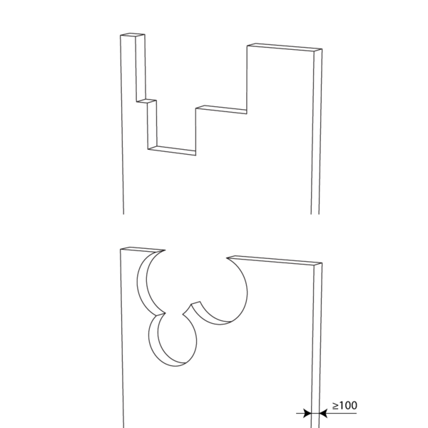
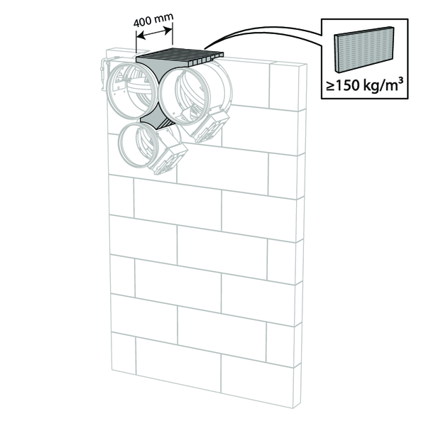
Apply rigid stone wool panels (≥ 150 kg/m³) to a depth of 400 mm (150 mm on the mechanism side of the wall) to seal the opening at the side with minimal distances.
The surface of this sealing is set between the axes (centres) of the dampers.
Caution: the opening is sealed according to the existing classification (see next point) when: - 2 fire dampers are installed at a minimum distance from one another but at a normal distance (≥ 75 mm) from the wall or floor/ceiling. - One single (no cluster) fire damper is located at a minimum distance (≤ 75 mm) from a wall or floor/ceiling.
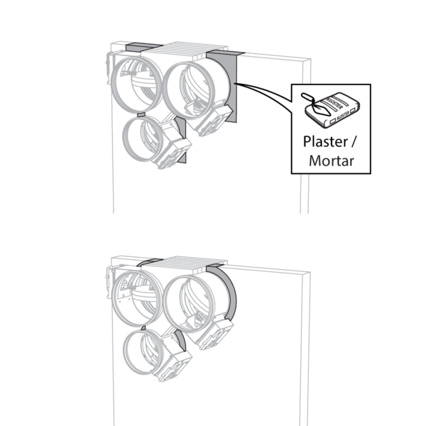
Seal the rest of the opening with standard mortar or gypsum.
Installation in rigid floor (125 mm)
The product was tested and approved in:
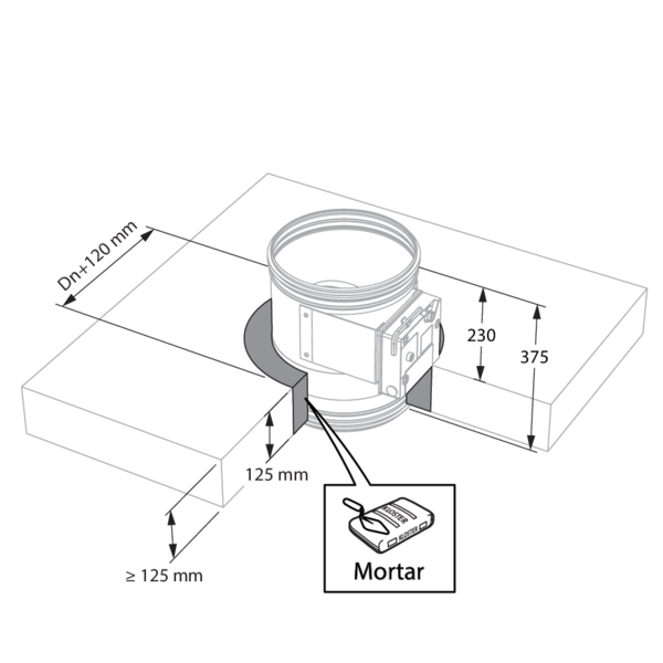
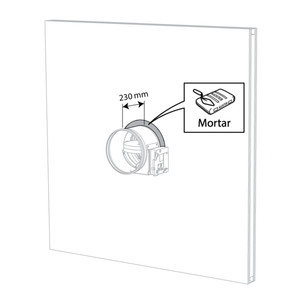
- Aerated concrete ≥ 125 mm | EI 90 (ho i o) S - (500 Pa) | Mortar | Type of installation: built-in, 0-360°. | Ø 200-630 mm
Installation in rigid floor (150 mm)
The product was tested and approved in:
- Aerated concrete ≥ 150 mm | EI 120 (ho i o) S - (500 Pa) | Mortar | Type of installation: built-in, 0-360°. Minimal distances authorised. | Ø 200-630 mm
The dampers can be installed at a minimum distance (≥ 30 mm) from an adjacent wall or from another damper.
Make the necessary openings (≤ Dn + 80 mm) in the floor.
Mount the dampers in the opening.
Apply rigid stone wool panels (≥ 150 kg/m³) to a depth of 400 mm (150 mm on the mechanism side of the wall) to seal the opening at the side with minimal distances.
The surface of this sealing is set between the axes (centres) of the dampers.
Caution: the opening is sealed according to the existing classification (see next point) when: - 2 fire dampers are installed at a minimum distance from one another but at a normal distance (≥ 75 mm) from the wall or floor/ceiling. - One single (no cluster) fire damper is located at a minimum distance (≤ 75 mm) from a wall or floor/ceiling.
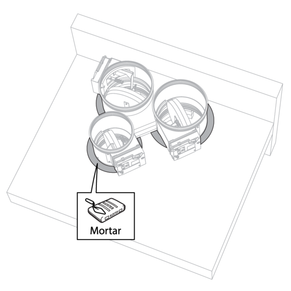
Seal the rest of the opening with standard mortar.
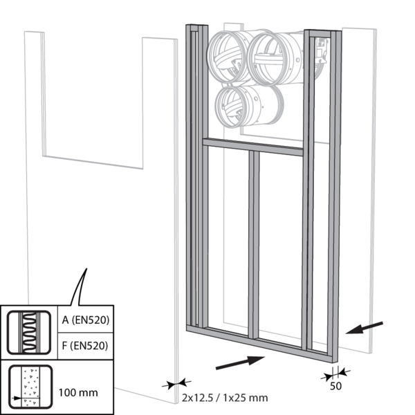
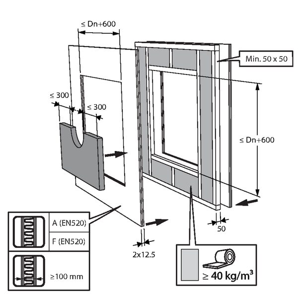
Installation in flexible wall (metal stud and plasterboard)
The product was tested and approved in:
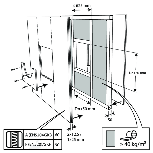
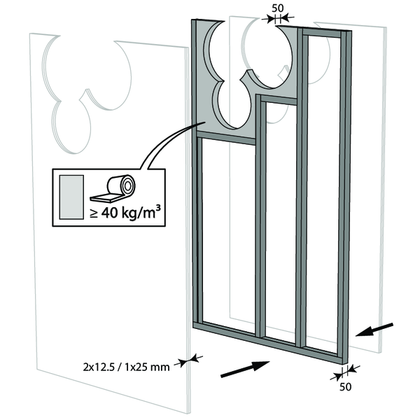
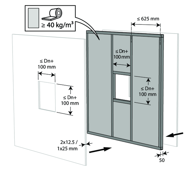
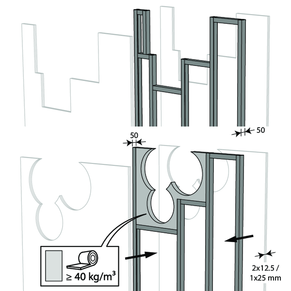
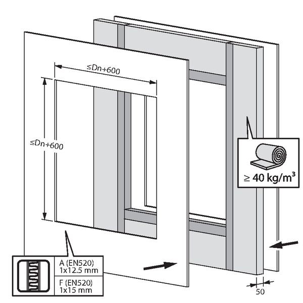
- Metal studs gypsum plasterboard Type F (EN 520) ≥ 100 mm | EI 90 (ve i o) S - (300 Pa) | Stone wool ≥ 40 kg/m³ + cover plates | Type of installation: built-in, 0-360°. Minimal distances authorised with axis till 45°. | Ø 200-630 mm
- Metal studs gypsum plasterboard Type A (EN 520) ≥ 100 mm | EI 60 (ve i o) S - (500 Pa) | Stone wool ≥ 40 kg/m³ + cover plates | Type of installation: built-in, 0-360°. Minimal distances authorised with axis till 45°. | Ø 200-630 mm
The dampers can be installed at a minimum distance (≥ 30 mm) from an adjacent wall or from another damper.

Build the drywall and mount horizontal and vertical studs around the opening.
In the opening around the dampers (Dn + 50 mm), the void between the gypsum boards is filled with stone wool with a minimum density of 40 kg/m³.
In the opening around the dampers (Dn + 50 mm), the void between the gypsum boards is filled with stone wool with a minimum density of 40 kg/m³.

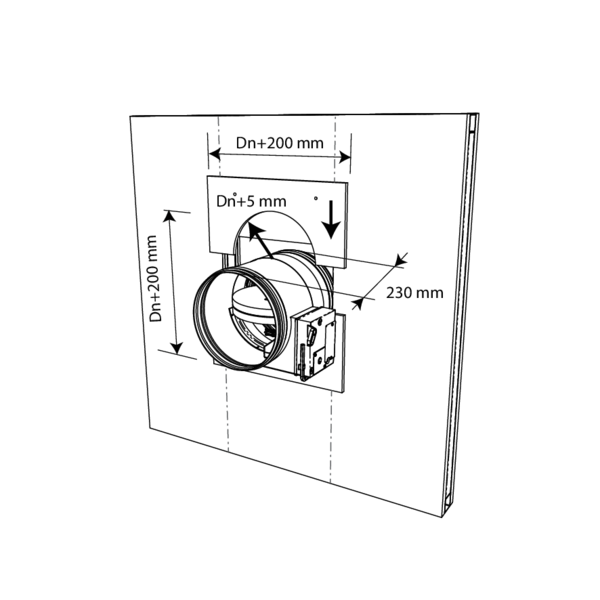
Mount the dampers in the opening.
Apply rigid stone wool panels (≥ 150 kg/m³) to a depth of 400 mm (150 mm on the mechanism side of the wall) to seal the opening at the side with minimal distances.
Caution: the opening is sealed according to the existing classification (see next point) when: - 2 fire dampers are installed at a minimum distance from one another but at a normal distance (≥ 75 mm) from the wall or floor/ceiling. - One single (no cluster) fire damper is located at a minimum distance (≤ 75 mm) from a wall or floor/ceiling.
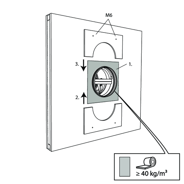
Apply cover plates (gypsum plasterboards) to finish the surface at both sides.
Seal off the space between the plasterboards with jointfiller.
Seal off the space between the plasterboards with jointfiller.
Installation in flexible wall - metal stud and gypsum
The product was tested and approved in:
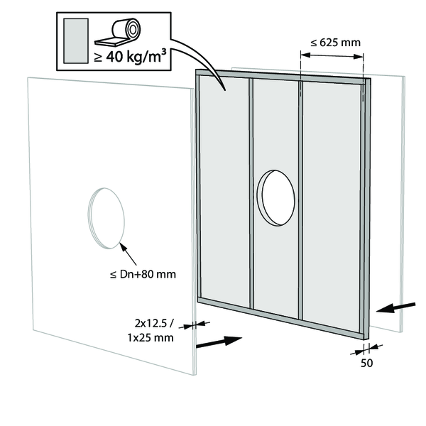
- Metal studs gypsum plasterboard Type A (EN 520) ≥ 100 mm | EI 60 (ve i o) S - (500 Pa) | Gypsum | Type of installation: built-in, 0-360°. Minimal distances authorised with axis till 45°. | Ø 200-630 mm
- Metal studs gypsum plasterboard Type F (EN 520) ≥ 100 mm | EI 120 (ve i o) S - (500 Pa) | Gypsum | Type of installation: built-in, 0-360°. Minimal distances authorised with axis till 45°. | Ø 200-630 mm

The dampers can be installed at a minimum distance (≥ 30 mm) from an adjacent wall or from another damper.
Build the drywall and mount horizontal and vertical studs around the opening.
When installing a single fire damper at a minimum distance from the ceiling, it is not necessary, from a fire technical point of view, to provide studs around the opening.
In the opening around the dampers, the void between the gypsum boards is partially filled (up to Dn + 80 mm) with stone wool with a minimum density of 40 kg/m³.
Mount the dampers in the opening.
Apply rigid stone wool panels (≥ 150 kg/m³) to a depth of 400 mm (150 mm on the mechanism side of the wall) to seal the opening at the side with minimal distances.
The surface of this sealing is set between the axes (centres) of the dampers.
Caution: the opening is sealed according to the existing classification (see next point) when: - 2 fire dampers are installed at a minimum distance from one another but at a normal distance (≥ 75 mm) from the wall or floor/ceiling. - One single (no cluster) fire damper is located at a minimum distance (≤ 75 mm) from a wall or floor/ceiling.
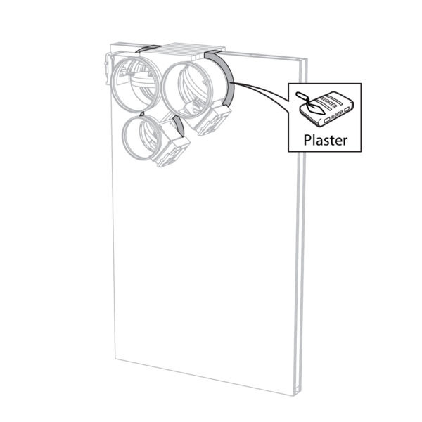
Seal the rest of the opening with standard gypsum across the entire wall thickness.
Installation in flexible wall - metal stud and mortar
The product was tested and approved in:
- Metal studs gypsum plasterboard Type A (EN 520) ≥ 100 mm | EI 60 (ve i o) S - (300 Pa) | Mortar | Type of installation: built-in, 0-360°. Minimal distances authorised with axis till 45°. | Ø 200-630 mm
- Metal studs gypsum plasterboard Type F (EN 520) ≥ 100 mm | EI 90 (ve i o) S - (300 Pa) | Mortar | Type of installation: built-in, 0-360°. Minimal distances authorised with axis till 45°. | Ø 200-630 mm
The dampers can be installed at a minimum distance (≥ 30 mm) from an adjacent wall or from another damper.
Build the drywall and mount horizontal and vertical studs around the opening.
When installing a single fire damper at a minimum distance from the ceiling, it is not necessary, from a fire technical point of view, to provide studs around the opening.
For a circular wall opening, the space between the plasterboard sheets is partially (up to Dn + 40 mm) filled with stone wool with a minimum density of 40kg/m³.
Mount the dampers in the opening.
Apply rigid stone wool panels (≥ 150 kg/m³) to a depth of 400 mm (150 mm on the mechanism side of the wall) to seal the opening at the side with minimal distances.
The surface of this sealing is set between the axes (centres) of the dampers.
Caution: the opening is sealed according to the existing classification (see next point) when: - 2 fire dampers are installed at a minimum distance from one another but at a normal distance (≥ 75 mm) from the wall or floor/ceiling. - One single (no cluster) fire damper is located at a minimum distance (≤ 75 mm) from a wall or floor/ceiling.
Apply rigid stone wool panels (≥ 150 kg/m³) to a depth of 400 mm (150 mm on the mechanism side of the wall) to seal the opening at the side with minimal distances.
The surface of this sealing is set between the axes (centres) of the dampers.
Caution: the opening is sealed according to the existing classification (see next point) when: - 2 fire dampers are installed at a minimum distance from one another but at a normal distance (≥ 75 mm) from the wall or floor/ceiling. - One single (no cluster) fire damper is located at a minimum distance (≤ 75 mm) from a wall or floor/ceiling.
Seal the rest of the opening with standard mortar across the entire wall thickness.
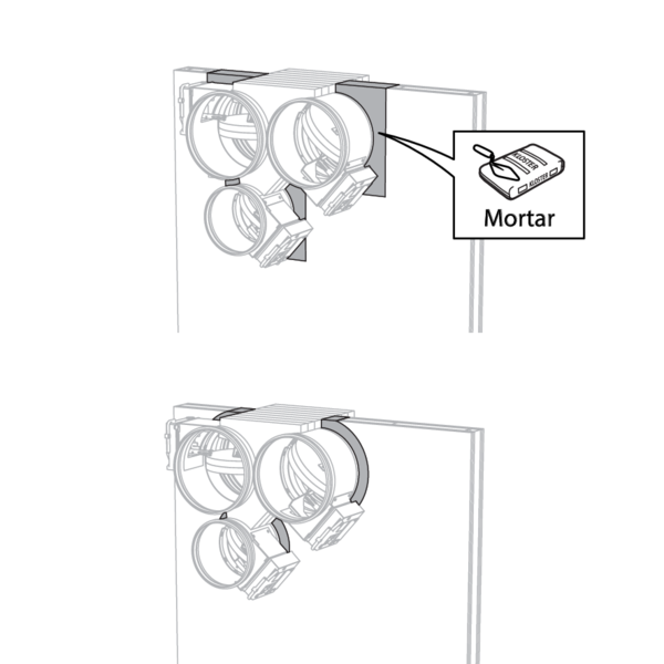
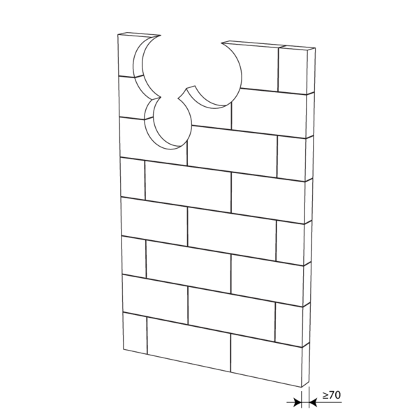
Installation in gypsum block wall
The product was tested and approved in:
- Gypsum blocks ≥ 70 mm | EI 120 (ve i o) S - (500 Pa) | Block glue | Type of installation: built-in, 0-360°. Minimal distances authorised with axis till 45°. | Ø 200-630 mm
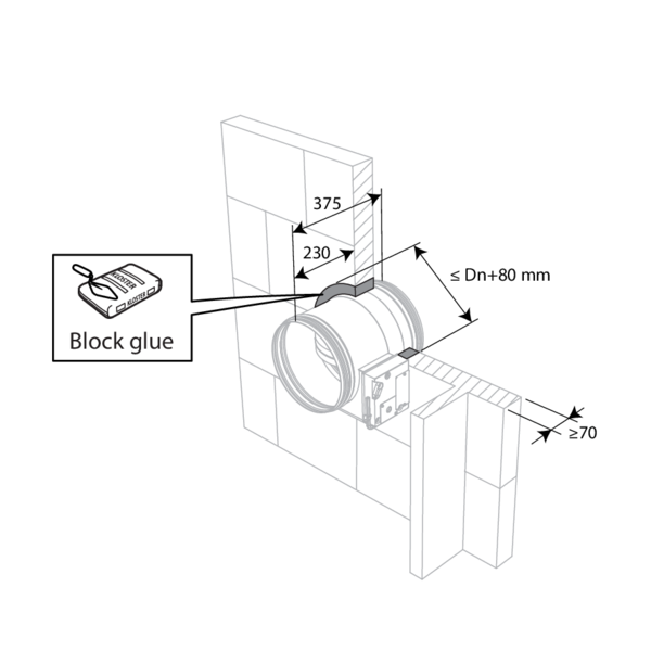
Seal the fire damper with a gypsum-based block glue.
The dampers can be installed at a minimum distance from an adjacent wall or from another damper.
Make the necessary openings (≤ Dn + 80 mm) in the wall.
Mount the dampers in the opening.
Apply rigid stone wool panels (≥ 150 kg/m³) to a depth of 400 mm (150 mm on the mechanism side of the wall) to seal the opening at the side with minimal distances.
The surface of this sealing is set between the axes (centres) of the dampers.
Caution: the opening is sealed according to the existing classification (see next point) when: - 2 fire dampers are installed at a minimum distance from one another but at a normal distance (≥ 75 mm) from the wall or floor/ceiling. - One single (no cluster) fire damper is located at a minimum distance (≤ 75 mm) from a wall or floor/ceiling.
Apply rigid stone wool panels (≥ 150 kg/m³) to a depth of 400 mm (150 mm on the mechanism side of the wall) to seal the opening at the side with minimal distances.
The surface of this sealing is set between the axes (centres) of the dampers.
Caution: the opening is sealed according to the existing classification (see next point) when: - 2 fire dampers are installed at a minimum distance from one another but at a normal distance (≥ 75 mm) from the wall or floor/ceiling. - One single (no cluster) fire damper is located at a minimum distance (≤ 75 mm) from a wall or floor/ceiling.
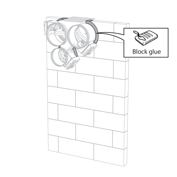
Seal the rest of the opening with block glue across the entire wall thickness.
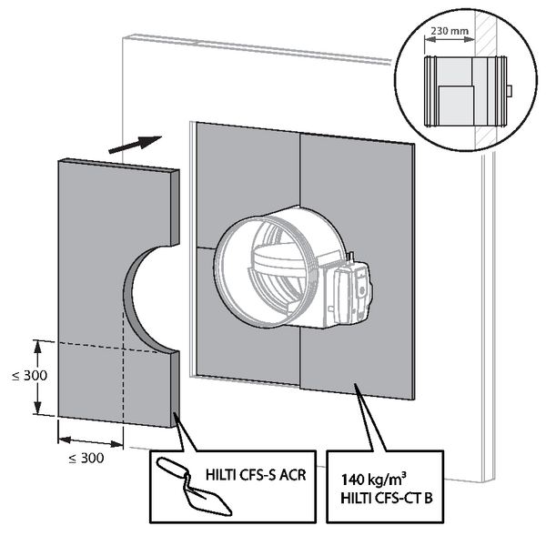
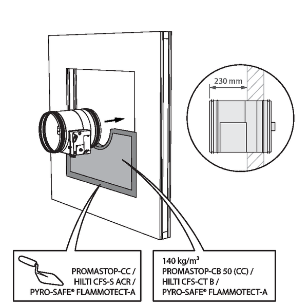
Installation in flexible and rigid wall, sealing with rigid stone wool boards with coating
The product was tested and approved in:
- Aerated concrete ≥ 100 mm | EI 90 (ve i o) S - (300 Pa) | Stone wool + coating ≥ 140 kg/m³ | Type of installation: built-in, 0-360°. Minimal distances authorised with axis till 45°. | Ø 200-630 mm
- Aerated concrete ≥ 100 mm | EI 60 (ve i o) S - (300 Pa) | Stone wool Mulcol Multimastic FB1 + coating | Type of installation: built-in, 0-360°. | Ø 200-630 mm
- Aerated concrete ≥ 100 mm | EI 120 (ve i o) S - (300 Pa) | Stone wool Pyro-Safe® MFP + coating | Type of installation: built-in, 0-360°. | Ø 200-630 mm
- Metal studs gypsum plasterboard Type A (EN 520) ≥ 100 mm | EI 60 (ve i o) S - (300 Pa) | Stone wool + coating ≥ 140 kg/m³ | Type of installation: built-in, 0-360°. Minimal distances authorised with axis till 45°. | Ø 200-630 mm
- Metal studs gypsum plasterboard Type F (EN 520) ≥ 100 mm | EI 90 (ve i o) S - (300 Pa) | Stone wool + coating ≥ 140 kg/m³ | Type of installation: built-in, 0-360°. Minimal distances authorised with axis till 45°. | Ø 200-630 mm
- Metal studs gypsum plasterboard Type F (EN 520) ≥ 100 mm | EI 60 (ve i o) S - (300 Pa) | Stone wool Mulcol Multimastic FB1 + coating | Type of installation: built-in, 0-360°. | Ø 200-630 mm
- Metal studs gypsum plasterboard Type F (EN 520) ≥ 100 mm | EI 120 (ve i o) S - (300 Pa) | Stone wool Pyro-Safe® MFP + coating | Type of installation: built-in, 0-360°. | Ø 200-630 mm
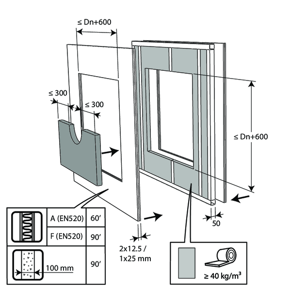
For flexible walls, provide horizontal and vertical studs around the opening. Exception: for fire resistance EI60S/EI90S and if sealing with PROMASTOP or Hilti type boards, it is not necessary, from a fire technical point of view, to provide studs around the opening.
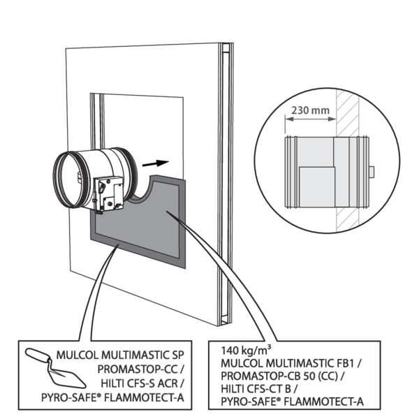
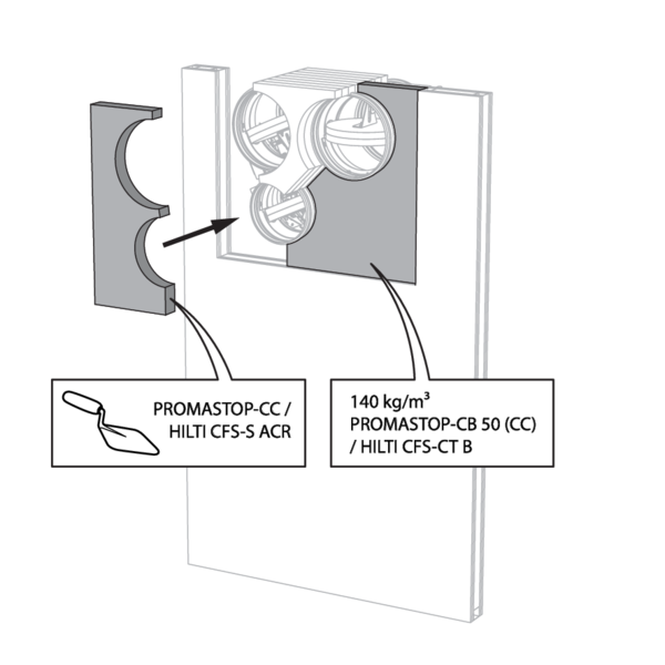
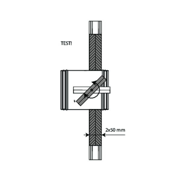
The opening around the damper is sealed with 2 layers of 50 mm-thick mineral wool panels with fire resistant coating on one side (type PROMASTOP-CB 50 / PROMASTOP-CB/CC 50 / HILTI CFS-CT B / Mulcol Multimastic FB1 / PYRO-SAFE® FLAMMOTECT-A).
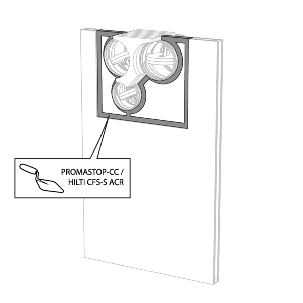
The joints on these 2 layers must be installed staggered and covered all around the edge with coating (type PROMASTOP-CC / HILTI CFS-S-ACR / Mulcol Multimastic SP / PYRO-SAFE® FLAMMOTECT-A).
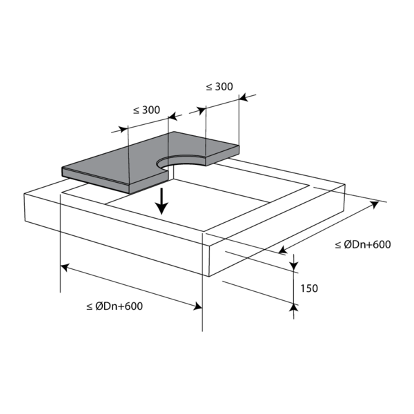
The damper does not need to be centered in the opening (with max dimensions fire damper + 600 mm). The maximal distance between the damper and the edge of the opening is 400 mm.
The dampers can be installed at a minimum distance (≥ 30 mm) from an adjacent wall or from another damper.
Build the drywall and mount horizontal and vertical studs around the opening.
When installing a single fire damper at a minimum distance from the ceiling, it is not necessary, from a fire technical point of view, to provide studs around the opening in case of desired fire resistance EI60S/EI90S.
Mount the dampers in the opening.
When installing a single fire damper at a minimum distance from the ceiling, it is not necessary, from a fire technical point of view, to provide studs around the opening in case of desired fire resistance EI60S/EI90S.
Mount the dampers in the opening.
Apply rigid stone wool panels (≥ 150 kg/m³) to a depth of 400 mm (150 mm on the mechanism side of the wall) to seal the opening at the side with minimal distances.
Caution: the opening is sealed according to the existing classification (see next point) when: - 2 fire dampers are installed at a minimum distance from one another but at a normal distance (≥ 75 mm) from the wall or floor/ceiling. - One single (no cluster) fire damper is located at a minimum distance (≤ 75 mm) from a wall or floor/ceiling.
Caution: the opening is sealed according to the existing classification (see next point) when: - 2 fire dampers are installed at a minimum distance from one another but at a normal distance (≥ 75 mm) from the wall or floor/ceiling. - One single (no cluster) fire damper is located at a minimum distance (≤ 75 mm) from a wall or floor/ceiling.
Seal the rest of the opening with 2 layers of 50 mm-thick coated rigid mineral wool panels (see above).
Installation in flexible wall - metal stud with a single layer of plasterboard and sealing with rigid stone wool boards with coating
Fire batt/stone wool boards of type HILTI CFS-CT B may be replaced by a similar type of fire batt with at least the same fire reaction class, density and thickness (tested according to EN 1366-3).
The partition is built with a single layer of plasterboard either side. Both I- and C-studs are allowed.
The opening around the damper is sealed with 2 layers of 50 mm-thick mineral wool panels with fire resistant coating on one side (type HILTI CFS-CT B).
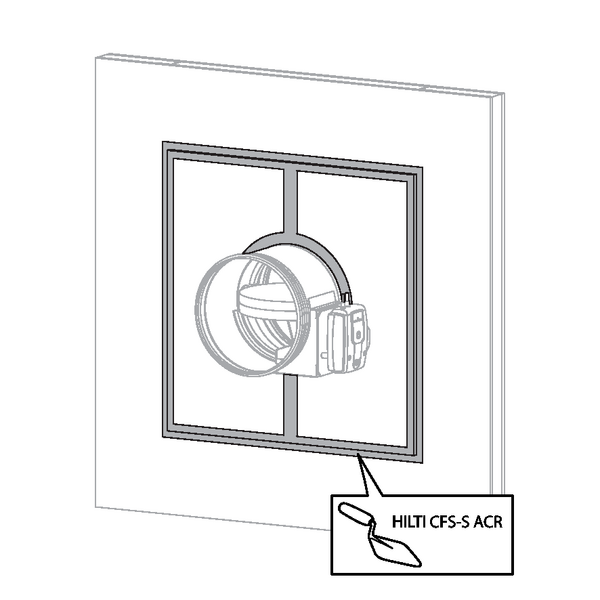
The joints on these 2 layers must be installed staggered and covered all around the edge with coating (type HILTI CFS-S-ACR).
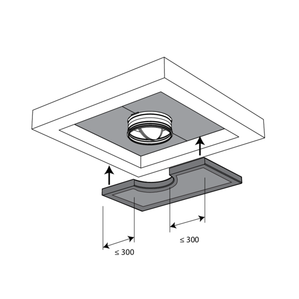
The damper does not need to be centered in the opening (with max dimensions fire damper + 600 mm). The maximal distance between the damper and the edge of the opening is 300 mm.
Max. 2 dampers can be installed at a minimum distance (30 mm) from each other.
Installation in flexible wall (timber stud), sealing with rigid stone wool boards with coating
The product was tested and approved in:
- Timber studs gypsum plasterboard Type A (EN 520) ≥ 100 mm | EI 60 (ve i o) S - (300 Pa) | Stone wool + coating ≥ 140 kg/m³ | Type of installation: built-in, 0/180° (CR) | Ø 200-630 mm
- Timber studs gypsum plasterboard Type F (EN 520) ≥ 100 mm | EI 90 (ve i o) S - (300 Pa) | Stone wool + coating ≥ 140 kg/m³ | Type of installation: built-in, 0/180° (CR) | Ø 200-630 mm
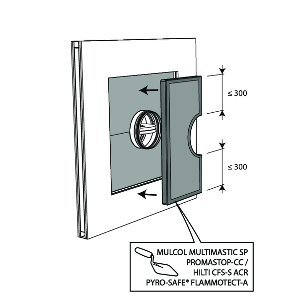
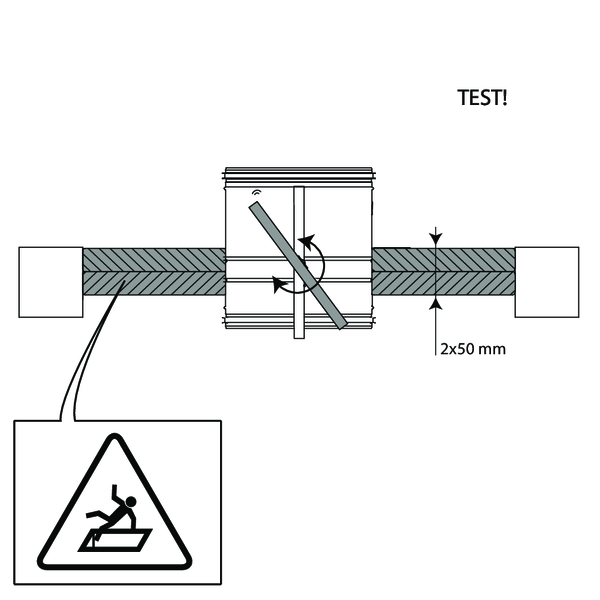
The opening around the damper is sealed with 2 rigid stone wool boards of 50 mm. These boards should be placed in a slanted position and the joints should be covered all around with filling paste.
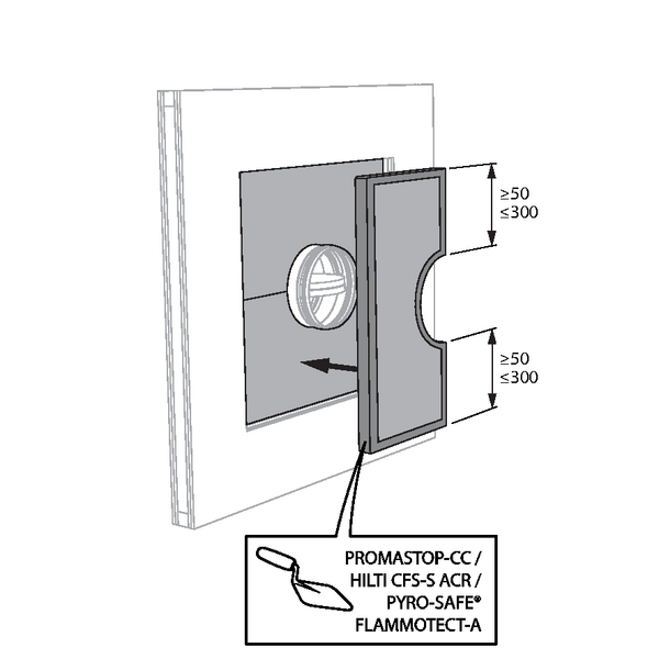
The damper does not need to be centered in the opening (with max dimensions Ø fire damper + 600 mm). The maximal distance between the damper and the edge of the opening is 300 mm.
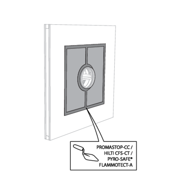
Installation in rigid floor, sealing with rigid stone wool boards with coating
The product was tested and approved in:
- Aerated concrete ≥ 150 mm | EI 120 (ho i o) S - (300 Pa) | Stone wool + coating ≥ 140 kg/m³ | Type of installation: built-in, 0-360°. Minimal distances authorised. | Ø 200-630 mm
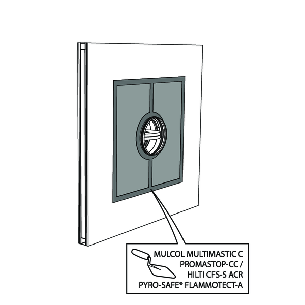
The opening around the damper is sealed with 2 layers of 50 mm-thick mineral wool panels with fire resistant coating on one side (type PROMASTOP-CB 50 / PROMASTOP-CB/CC 50 / HILTI CFS-CT B).
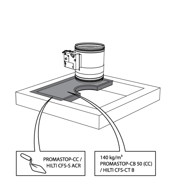
The joints on these 2 layers must be installed staggered and covered all around the edge with coating (type PROMASTOP-CC / HILTI CFS-S-ACR).
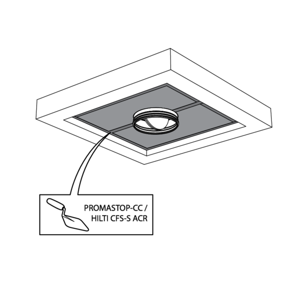
The damper does not need to be centered in the opening (with max dimensions fire damper + 600 mm). The maximal distance between the damper and the edge of the opening is 400 mm.
The dampers can be installed at a minimum distance (≥ 30 mm) from an adjacent wall or from another damper.
For details, please refer to 'Installation in flexible and rigid wall, sealing with rigid stone wool boards with coating'
For details, please refer to 'Installation in flexible and rigid wall, sealing with rigid stone wool boards with coating'
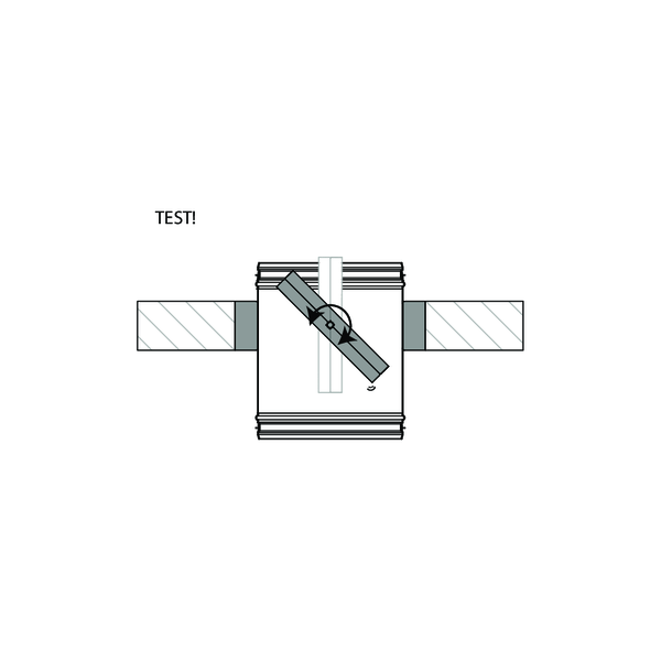
Inspection of the damper via UL option or via the fusible link opening of the ONE mechanism
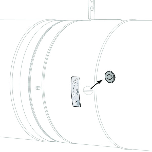
An inspection opening (only available when ordering the ‘UL’ option) allows the position and condition of the damper to be visually determined with an endoscope. For fire dampers equipped with the ONE mechanism, it is also possible to carry out this camera inspection through the opening of the fusible link.
Option UL:
Remove the air-tight plug from the damper.
Option UL:
Remove the air-tight plug from the damper.
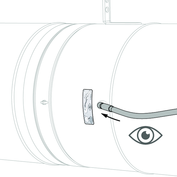
Insert the camera of the endoscope (for example Inspecam Rf-t) through the opening and inspect the inside of the damper.

After inspection, replace the air-tight plug thoroughly on the damper opening. The position is crucial in order to maintain the air-tightness of the fire damper.
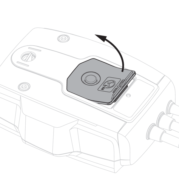
ONE mechanism:
Open the battery compartment.
Open the battery compartment.
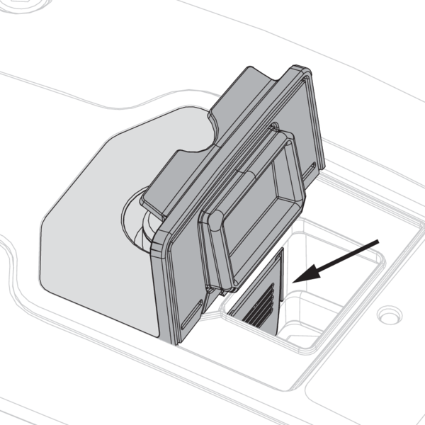
Press the flexible button inside the battery compartment.
Pull the fusible link and the rubber cover simultaneously out of the mechanism.
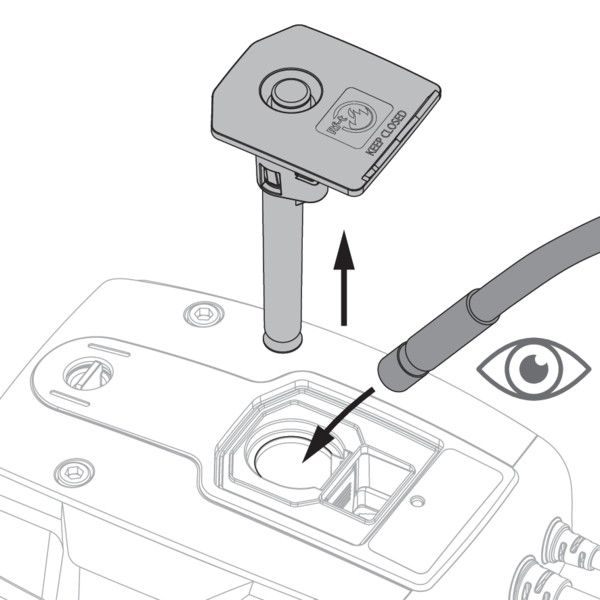
Insert the camera of the endoscope (for example Inspecam Rf-t) through the opening and inspect the inside of the damper.
Slide the fusible link back into the mechanism until it clicks into place. Close the cover of the battery compartment.
Insert the camera of the endoscope (for example Inspecam Rf-t) through the opening and inspect the inside of the damper.
Slide the fusible link back into the mechanism until it clicks into place. Close the cover of the battery compartment.
General remarks
- The installation must comply with the installation manual and the classification report.
- Axis orientation: see the declaration of performance.
- Avoid obstruction of adjoining ducts.
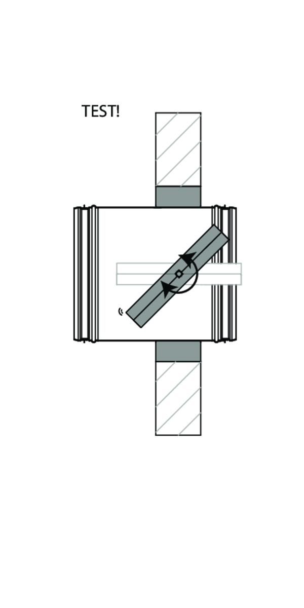
- Product installation: always with closed damper blade.
- Verify if the blade can move freely.
- Please observe safety distances with respect to other construction elements. The operating mechanism must also remain accessible: allow for a clearance of 200 mm around the housing.
- The air tightness class will be maintained if the damper is installed according to the installation manual.
- Rf-t fire dampers are always tested in standardised constructions according to EN 1366-2. The achieved results are valid for similar supporting constructions with a fire resistance, thickness and density equal or superior to the supporting construction used during the test.
- If the wall thickness exceeds the minimum thickness specified in our installation instructions, the following conditions apply to the sealing depth: - For flexible walls and sandwich panel system walls, the seal must always be applied over the full depth of the wall. - With rigid walls, rigid floors and plaster block walls, the minimum sealing depth as indicated in our installation instructions (often equal to the minimum wall thickness) is sufficient. Apply the seal at the height of the damper blade (from the wall limit indication).
- When installing a fire damper in a flexible metal stud wall, some installation methods do not require reinforcing profiles around the wall opening from a fire protection point of view (see below). Always follow the general instructions of the manufacturer of these wall systems when building this type of wall.
- The damper must remain accessible for inspection and maintenance.
- Schedule at least 2 visual checks each year.