KAMOUFLAGE 2V60 - Installation
Operation: manual opening
Kamouflage 2V:
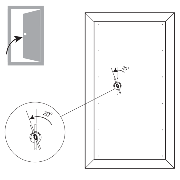
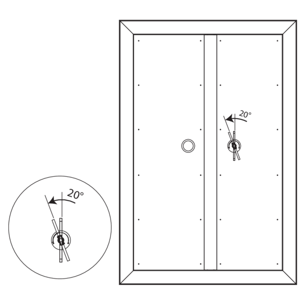
Insert the key in the lock. Turn the key 20° anti-clockwise: the shutter opens. Remove the key from the lock.
Insert the key in the lock. Turn the key 20° anti-clockwise: the shutter opens. Remove the key from the lock.
Operation: manual closing 1V
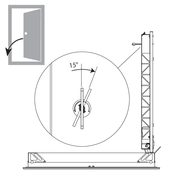
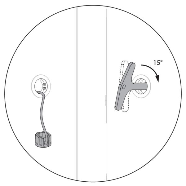
Close the shutter by pulling at the key.
Turn the key 15° clockwise, the key unblocks from the lock. Withdraw the key.
Operation: manual closing 2V
Kamouflage 2V:
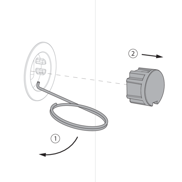
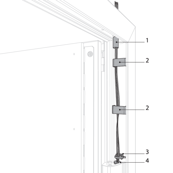
Electrical wiring

Caution: after passing and fixing the cables, you need to seal the drilled hole in the refractory plates around the electrical cables with fire resistant adhesive sealant (BCM f.e.).

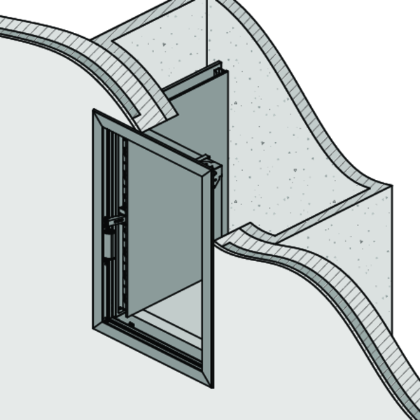
Position in the duct
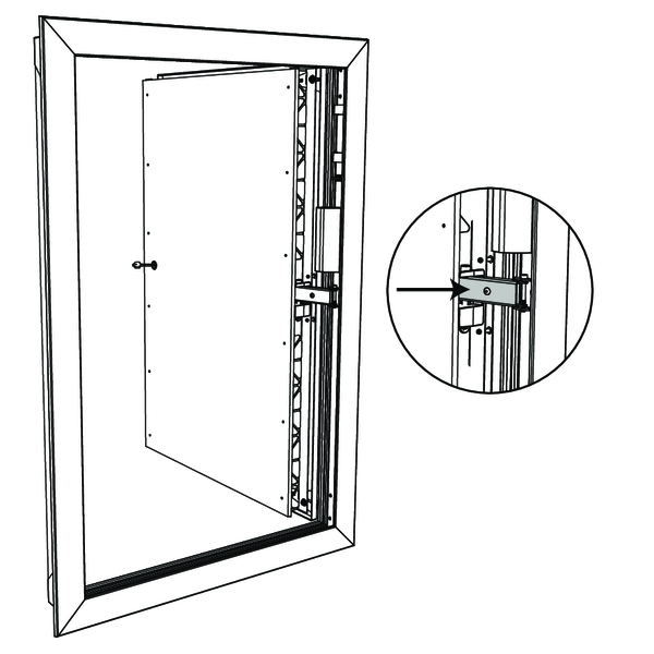
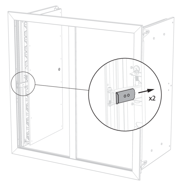
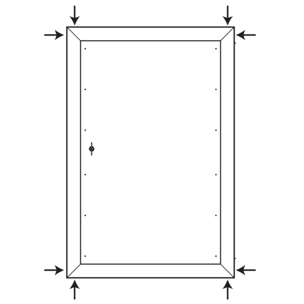
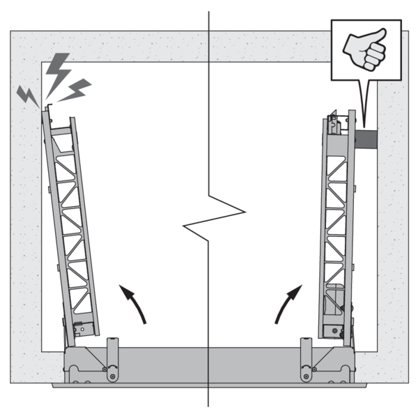
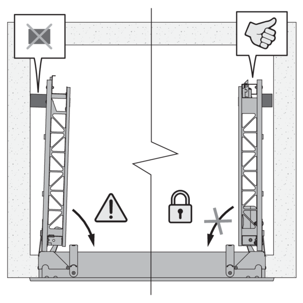
Shock absorbers for the doors
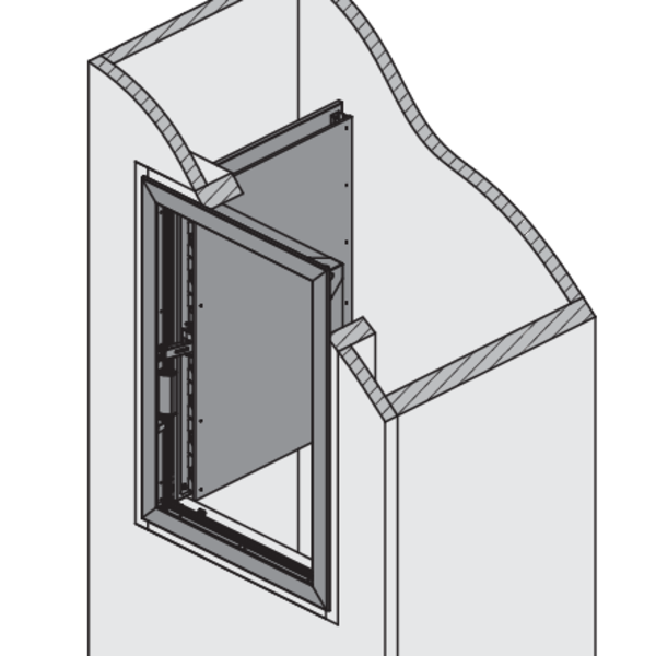
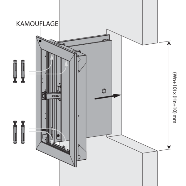
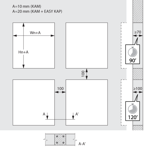
Installation into vertical concrete shaft with mounting frame
Due to changes in the test standard EN 1366-10, the acceptance of test results with duct materials under “d” classification for rigid structures (such as concrete) lies with the individual EU member states. We retain this info in this installation manual; final approval must be coordinated locally with the competent government or approval authority.
The product was tested and approved in:
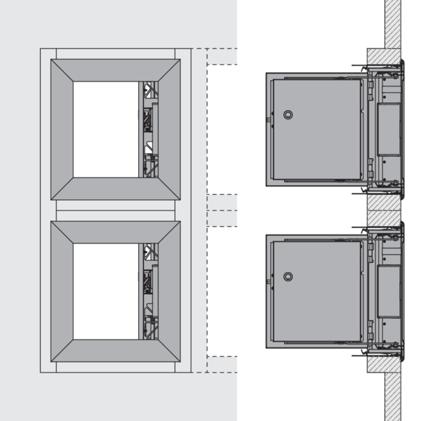
- Concrete ≥ 70 mm | EI 60 (ved i o) S 1500 AA multi | Kamouflage 60 | Type of installation: in duct/shaft-mounted 0/180°. Minimal in-between distances authorised. | 300x385 mm ≤ Kamouflage 1V ≤ 700x1075 mm; 350x385 mm ≤ Kamouflage 2V ≤ 1100x1105 mm
- Masonry, concrete blocks, concrete ≥ 100 mm | EI 60 (ved i o) S 1500 AA multi | Kamouflage 60 | Type of installation: in duct/shaft-mounted 0/180°. Minimal in-between distances authorised. | 300x385 mm ≤ Kamouflage 1V ≤ 700x1075 mm; 350x385 mm ≤ Kamouflage 2V ≤ 1100x1105 mm
installation smoke shutter with EASY-KAP mounting frame:
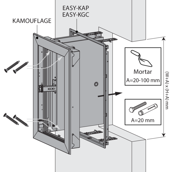
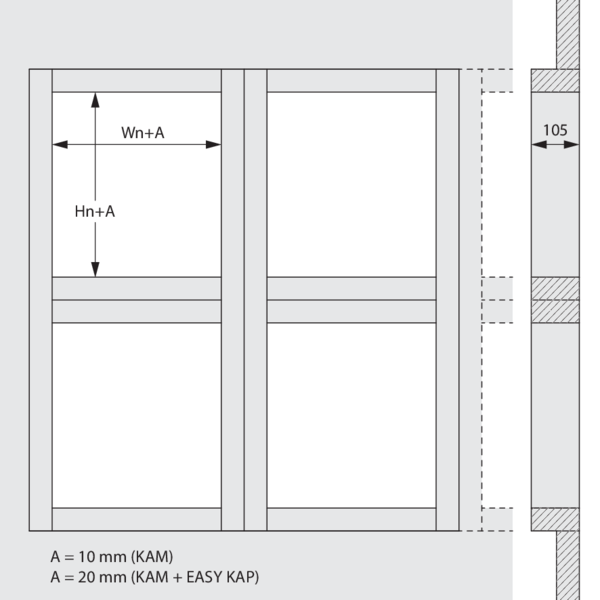
Make an opening with dimensions (W+20) x (H+20) mm.
In case the mounting frame is fixed with mortar:
Make an opening with dimensions (W+20) x (H+20) mm till (W+100) x (H+100) mm.
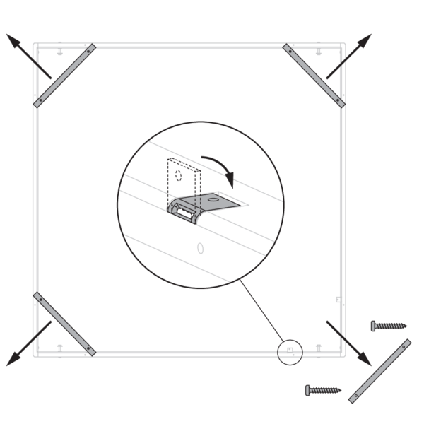
In case the mounting frame is screwed (opening with dimensions up to (W+20) x (H+20) mm):
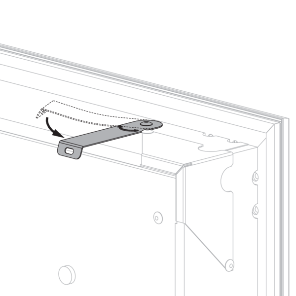
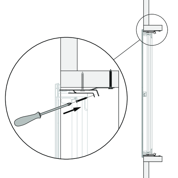
Two fixing lugs are provided at the bottom and at the top of the mounting frame: fold these against the shaft and fasten the mounting frame with 4 screws Ø 6 x 60 mm, taking care not to misshape it. These screws can be inserted through any of the punched holes in the lugs, depending on the thickness of the shaftwall. The finished opening must have the same size as the mounting frame (W+10) x (H+10) mm.
In case the mounting frame is fixed with mortar (opening with dimensions up to (W+100) x (H+100) mm):
Apply mortar around the opening to reduce the opening to the outer dimensions of the frame, then proceed as mentioned above to fasten the frame into the opening. Make sure that the gap between the frame and the opening is sealed completely with mortar.
The mortar must harden completely before attaching the shutter to the mounting frame.
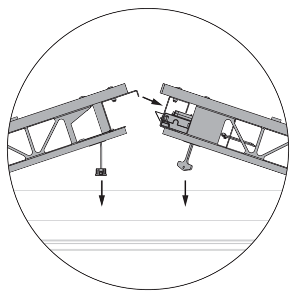
When the EASY-KGC mounting frame is used, unfold the drop-guard grid (90°) in the shaft.
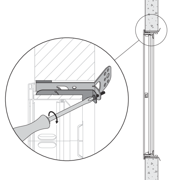
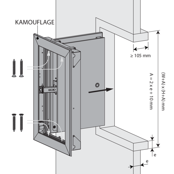
Fasten the shutter onto the mounting frame with the 4 screws supplied, as shown in the drawing. Tightening the screws pulls the shutter towards the wall until its final position. You can also slightly correct the angle of the shutter with respect to the mounting frame.
Connect the mechanism according to the wiring diagram.
Test the proper operation of the shutter.
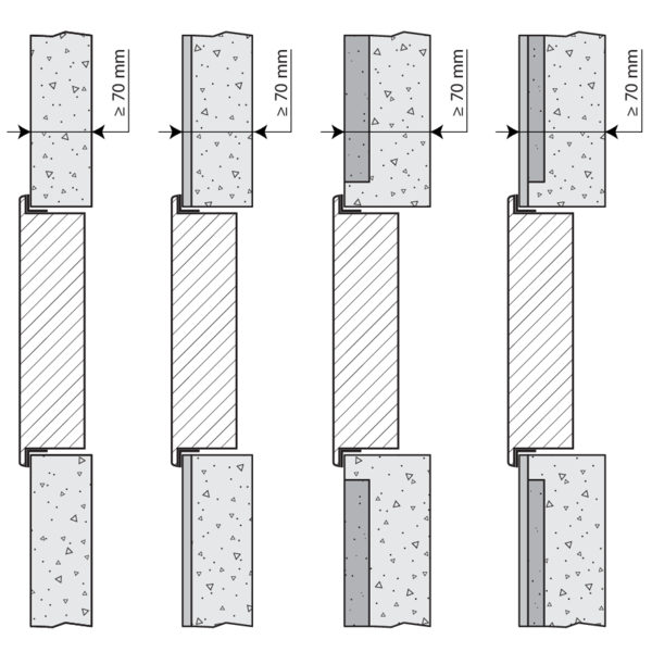
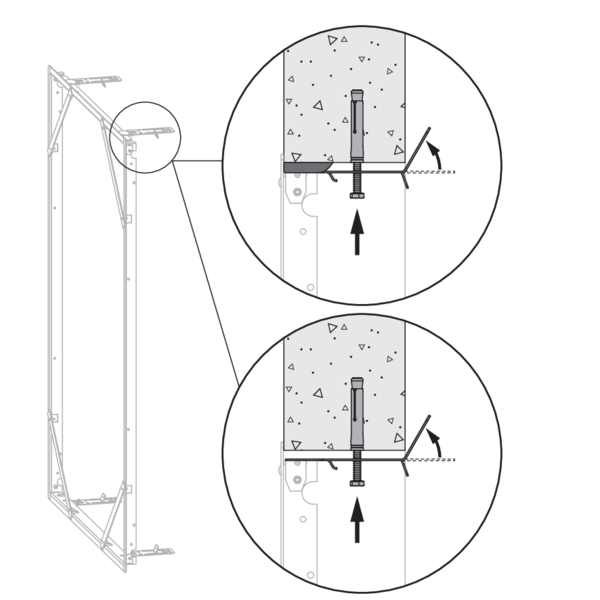
Installation into vertical concrete shaft without mounting frame
Due to changes in the test standard EN 1366-10, the acceptance of test results with duct materials under “d” classification for rigid structures (such as concrete) lies with the individual EU member states. We retain this info in this installation manual; final approval must be coordinated locally with the competent government or approval authority.
The product was tested and approved in:
- Concrete ≥ 70 mm | EI 60 (ved i o) S 1500 AA multi | Kamouflage 60 | Type of installation: in duct/shaft-mounted 0/180°. Minimal in-between distances authorised. | 300x385 mm ≤ Kamouflage 1V ≤ 700x1075 mm; 350x385 mm ≤ Kamouflage 2V ≤ 1100x1105 mm
- Masonry, concrete blocks, concrete ≥ 100 mm | EI 60 (ved i o) S 1500 AA multi | Kamouflage 60 | Type of installation: in duct/shaft-mounted 0/180°. Minimal in-between distances authorised. | 300x385 mm ≤ Kamouflage 1V ≤ 700x1075 mm; 350x385 mm ≤ Kamouflage 2V ≤ 1100x1105 mm
The fastening plates are not used for an installation without a mounting frame.
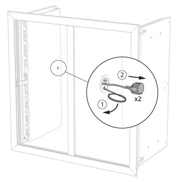
Open and position the shutter in the opening. If VM magnet: remove the key from the lock to open the shutter.
Fix the shutter in the opening using 4 screws and dowels Ø6 x 40 mm.
Connect the mechanism according to the wiring diagram.
Test the proper operation of the shutter.
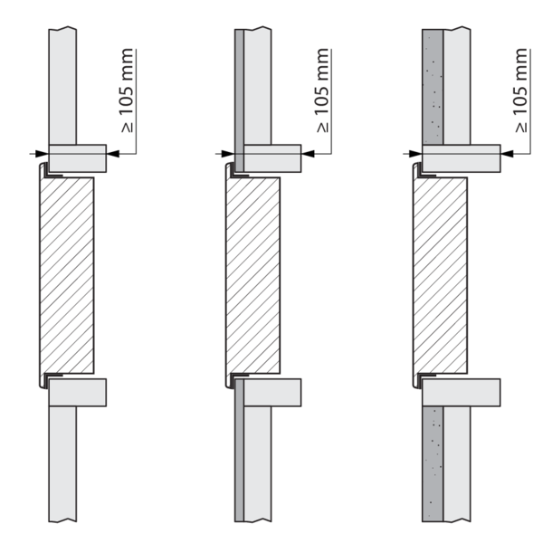
Installation into vertical duct with built-in mounting frame: general instructions for all types of ducts (other than concrete)
installation smoke shutter with EASY-KAP mounting frame:
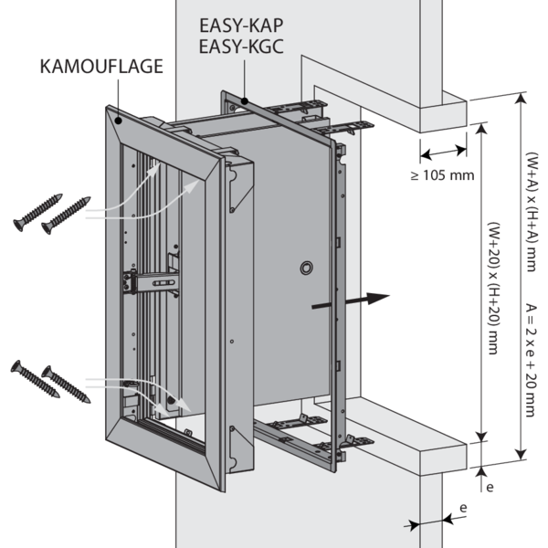
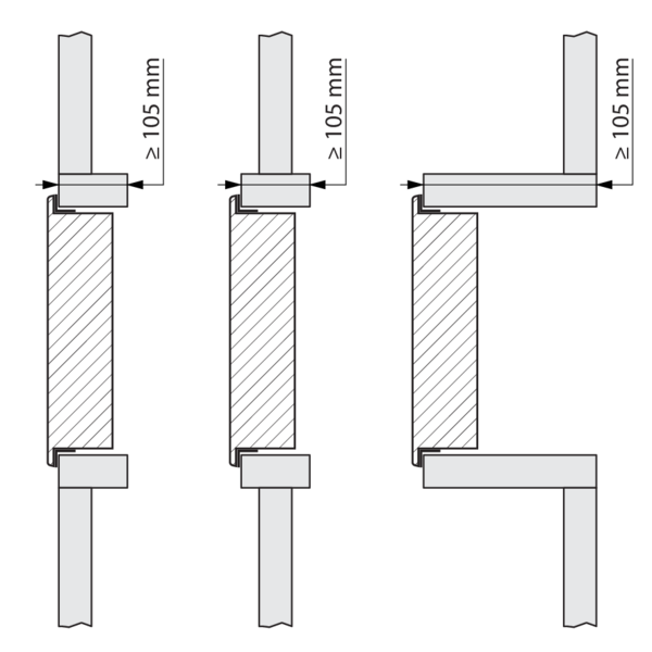
Fit a sleeve of the same type of material and thickness as the duct (thickness e) of minimum 105 mm deep in the opening.
See details per type of duct hereafter.
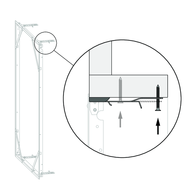
Two fixing lugs are provided at the bottom and at the top of the mounting frame: fold these against the sleeve. When fixed with screws, fasten the mounting frame to the sleeve with chipboard screws Ø 6 x e mm. These screws can be fixed in one of the openings provided for this purpose, depending on the depth of the sleeve.
Take care not to misshape the frame during its installation. The finished opening must have the same size as the mounting frame (W+10) x (H+10) mm.
When the EASY-KGC mounting frame is used, unfold the drop-guard grid (90°) in the duct.
Fasten the shutter onto the mounting frame with the 4 screws supplied, as shown in the drawing. Tightening the screws pulls the shutter towards the wall until its final position. You can also slightly correct the angle of the shutter with respect to the mounting frame.
Connect the mechanism according to the wiring diagram.
Test the proper operation of the shutter.
Installation into vertical duct (without a mounting frame): general instructions for all types of ducts (other than concrete)
The fastening plates are not used for an installation without a mounting frame.
Fit a sleeve of the same type of material and thickness as the duct (thickness e) of minimum 105 mm deep in the opening.
Open and position the shutter in the opening. If VM magnet: remove the key from the lock to open the shutter.
Fix the shutter in the opening using 4 screws Ø6 x 40 mm.
Caution: make sure that the screws don't exceed the sleeve's thickness!
Connect the mechanism according to the wiring diagram.
Test the proper operation of the shutter.
Installation into vertical duct PROMATECT L500
The product was tested and approved in:
- Promatect L500 ≥ 30 mm | EI 60 (ved i o) S 1500 AA multi | Kamouflage 60 | Type of installation: in duct/shaft-mounted 0/180°. Minimal in-between distances authorised. | 300x385 mm ≤ Kamouflage 1V ≤ 700x1075 mm; 350x385 mm ≤ Kamouflage 2V ≤ 1100x1105 mm
Assemble the sleeve with staples and affix the assembled sleeve to the duct wall with staples.
Coat the edges of the opening with adhesive plaster type Promacol S.
Seal the mounting frame with Promacol S taking care not to misshape it.
Assemble the sleeve with staples and affix the assembled sleeve to the duct wall with staples.
Installation into vertical duct GEOFLAM (LIGHT) / GEOTEC
The product was tested and approved in:
- Geoflam ≥ 30 mm | EI 60 (ved i o) S 1500 AA multi | Kamouflage 60 | Type of installation: in duct/shaft-mounted 0/180°. Minimal in-between distances authorised. | 300x385 mm ≤ Kamouflage 1V ≤ 700x1075 mm; 350x385 mm ≤ Kamouflage 2V ≤ 1100x1105 mm
- Geoflam N ≥ 35 mm | EI 60 (ved i o) S 1500 AA multi | Kamouflage 60 | Type of installation: in duct/shaft-mounted 0/180°. Minimal in-between distances authorised. | 300x385 mm ≤ Kamouflage 1V ≤ 700x1075 mm; 350x385 mm ≤ Kamouflage 2V ≤ 1100x1105 mm
- Geotec ≥ 30 mm | EI 60 (ved i o) S 1500 AA multi | Kamouflage 60 | Type of installation: in duct/shaft-mounted 0/180°. Minimal in-between distances authorised. | 300x385 mm ≤ Kamouflage 1V ≤ 700x1075 mm; 350x385 mm ≤ Kamouflage 2V ≤ 1100x1105 mm
Coat the edges of the opening with adhesive plaster type PLACOL (in case of Geoflam) or GEOCOL (S) (in case of Geotec).
In case of Geotec you can also assemble the sleeve with glue and screws Ø 5 x (2 x e) mm and affix the assembled sleeve to the duct wall with glue and screws Ø 5 x (2 x e) mm every 100 mm.
Seal the joints between uprights and cross pieces and between the lining and the wall with vegetable fibre caulking and plaster or with GEOCOL (S) (in case of Geotec).
Two fixing lugs are provided at the bottom and at the top of the mounting frame: fold these against the sleeve. Caulk the mounting frame to the duct with vegetable fibre or (in case of Geotec) you can also coat the opening with Geocol (S) and fasten the mounting frame with screws of Ø 5 x e mm. Take care not to misshape the frame.
Coat the edges of the opening with adhesive plaster type PLACOL (in case of Geoflam) or GEOCOL (S) (in case of Geotec).
Seal the joints between uprights and cross pieces and between the lining and the wall with vegetable fibre caulking and plaster or with GEOCOL (S) (in case of Geotec).
In case of Geotec you can also assemble the sleeve with glue and screws Ø 5 x (2 x e) mm and affix the assembled sleeve to the duct wall with glue and screws Ø 5 x (2 x e) mm every 100 mm.
Installation into vertical duct TECNIVER
The product was tested and approved in:
- Tecniver ≥ 35 mm | EI 60 (ved i o) S 1500 AA multi | Kamouflage 60 | Type of installation: in duct/shaft-mounted 0/180°. Minimal in-between distances authorised. | 300x385 mm ≤ Kamouflage 1V ≤ 700x1075 mm; 350x385 mm ≤ Kamouflage 2V ≤ 1100x1105 mm
Put glue type CF GLUE on the uprights and cross pieces and between the lining and the wall. Screw the sleeve using chipboard screws Ø5 x 70 mm at 150 mm intervals.
Two fixing lugs are provided at the bottom and at the top of the mounting frame: fold these against the sleeve. First coat the opening with glue CF GLUE. Glue the mounting frame to the lining taking care not to misshape it.
Put glue type CF GLUE on the uprights and cross pieces and between the lining and the wall. Screw the sleeve using chipboard screws Ø5 x 70 mm at 150 mm intervals.
Installation into vertical duct GLASROC F V500
The product was tested and approved in:
- Glasroc F V500 ≥ 35 mm | EI 60 (ved i o) S 1500 AA multi | Kamouflage 60 | Type of installation: in duct/shaft-mounted 0/180°. Minimal in-between distances authorised. | 300x385 mm ≤ Kamouflage 1V ≤ 700x1075 mm; 350x385 mm ≤ Kamouflage 2V ≤ 1100x1105 mm
Put glue type GLASROC F V500 on the uprights and cross pieces and between the lining and the wall. Screw the sleeve using chipboard screws Ø5 x 70 mm at 150 mm intervals.
Two fixing lugs are provided at the bottom and at the top of the mounting frame: fold these against the sleeve. First coat the opening with glue GLASROC F V500. Glue the mounting frame to the lining taking care not to misshape it.
Put glue type GLASROC F V500 on the uprights and cross pieces and between the lining and the wall. Screw the sleeve using chipboard screws Ø5 x 70 mm at 150 mm intervals.
Installation into vertical duct EXTHAMAT
The product was tested and approved in:
- Exthamat ≥ 25 mm | EI 60 (ved i o) S 1500 AA multi | Kamouflage 60 | Type of installation: in duct/shaft-mounted 0/180°. Minimal in-between distances authorised. | 300x385 mm ≤ Kamouflage 1V ≤ 700x1075 mm; 350x385 mm ≤ Kamouflage 2V ≤ 1100x1105 mm
Coat the edges of the opening with adhesive plaster.
Seal the joints between uprights and cross pieces and between the lining and the wall with vegetable fibre caulking and plaster.
Two fixing lugs are provided at the bottom and at the top of the mounting frame: fold these against the sleeve. Caulk the mounting frame to the duct with vegetable fiber caulking and plaster and taking care not to misshape it.
Coat the edges of the opening with adhesive plaster.
Seal the joints between uprights and cross pieces and between the lining and the wall with vegetable fibre caulking and plaster.
Installation into vertical duct DESENFIRE (HD/THD/STR)
The product was tested and approved in:
- Desenfire HD ≥ 25 mm | EI 60 (ved i o) S 1500 AA multi | Kamouflage 60 | Type of installation: in duct/shaft-mounted 0/180°. Minimal in-between distances authorised. | 300x385 mm ≤ Kamouflage 1V ≤ 700x1075 mm; 350x385 mm ≤ Kamouflage 2V ≤ 1100x1105 mm
- Desenfire STR ≥ 25 mm | EI 60 (ved i o) S 1500 AA multi | Kamouflage 60 | Type of installation: in duct/shaft-mounted 0/180°. Minimal in-between distances authorised. | 300x385 mm ≤ Kamouflage 1V ≤ 700x1075 mm; 350x385 mm ≤ Kamouflage 2V ≤ 1100x1105 mm
Coat the edges of the opening with adhesive plaster, type FACILIS.
Seal the joints between uprights and cross pieces and between the lining and the wall with vegetable fibre caulking and plaster.
Two fixing lugs are provided at the bottom and at the top of the mounting frame: fold these against the sleeve. Caulk the mounting frame to the duct with vegetable fiber caulking and plaster and taking care not to misshape it.
Coat the edges of the opening with adhesive plaster, type FACILIS.
Seal the joints between uprights and cross pieces and between the lining and the wall with vegetable fibre caulking and plaster.
Installation into vertical duct FIREBOARD CS D5
The product was tested and approved in:
- Fireboard CS D5 ≥ 35 mm | EI 60 (ved i o) S 1500 AA multi | Kamouflage 60 | Type of installation: in duct/shaft-mounted 0/180°. Minimal in-between distances authorised. | 300x385 mm ≤ Kamouflage 1V ≤ 700x1075 mm; 350x385 mm ≤ Kamouflage 2V ≤ 1100x1105 mm
Put glue type Fireboard CS Glue GT1 (Knauf) on the uprights and cross pieces and between the lining and the wall. Screw the sleeve using chipboard screws Ø4 x 70 mm at 155 mm intervals.
Two fixing lugs are provided at the bottom and at the top of the mounting frame: fold these against the sleeve. First coat the opening with glue Fireboard CS Glue GT1 (Knauf). Glue the mounting frame to the lining taking care not to misshape it.
Put glue type Fireboard CS Glue GT1 (Knauf) on the uprights and cross pieces and between the lining and the wall. Screw the sleeve using chipboard screws Ø4 x 70 mm at 155 mm intervals.
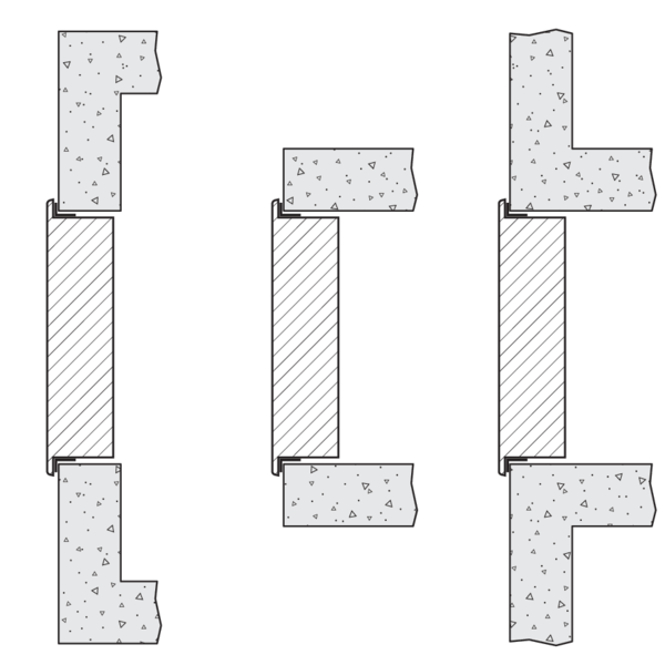
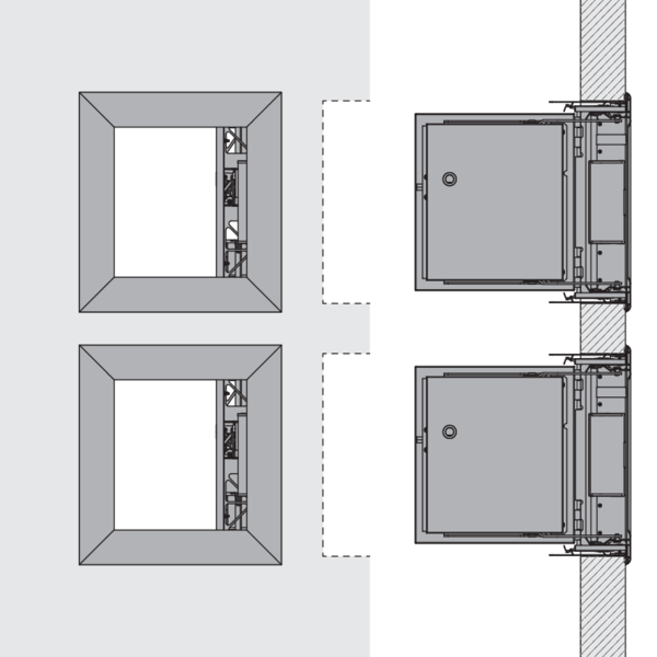
Installation at minimal distances
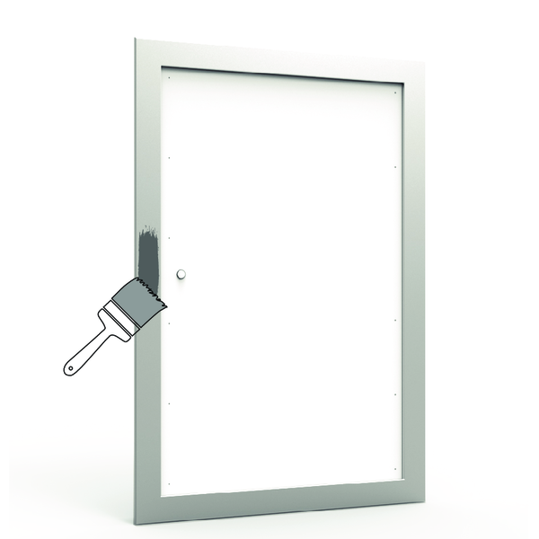
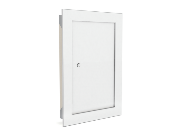
Finishing
The smoke control shutter can also be fully integrated into the wall. The technical details can be found on our website: https://www.rft.eu/assets/INDD%20tech%20notes/V12%20-%20KAMOUFLAGE/EN/KAM_int_1V-2V_EN.pdf Caution: the smoke control shutter must remain removable after integration.
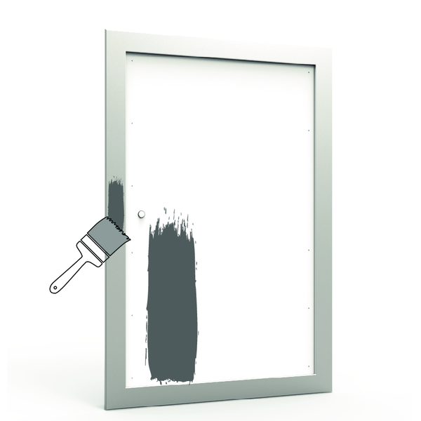
Preparation: The door consists of plasterboard: fill the screw holes with a suitable filler paste, allow to dry and sand the surface, then use a suitable primer. Treat the frame made of anodised aluminium also with a suitable primer.
Once the primer is dry, proceed with the finishing (paint or wallpaper).
Caution: don't fill / cover the joint between the covering plate and the aluminium profile in order to guarantee that the shutter can open.
General remarks
- The installation must comply with the installation manual and the classification report.
- The installation of the smoke control duct must comply with the classification report delivered by the manufacturer.
- Axis orientation: see the declaration of performance.