KAMOUFLAGE AP 1V60 - Installation
Operation: manual opening
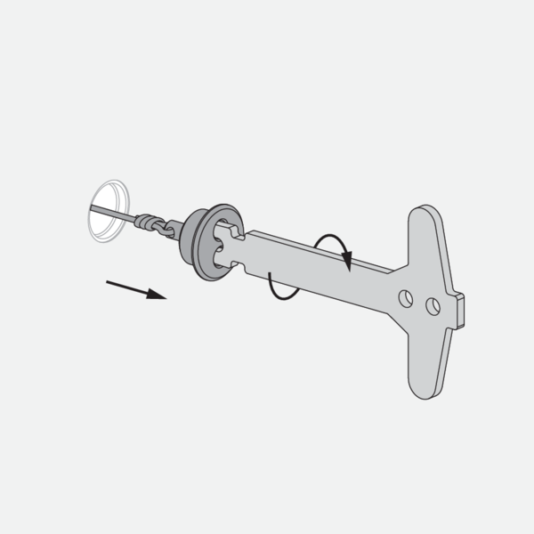
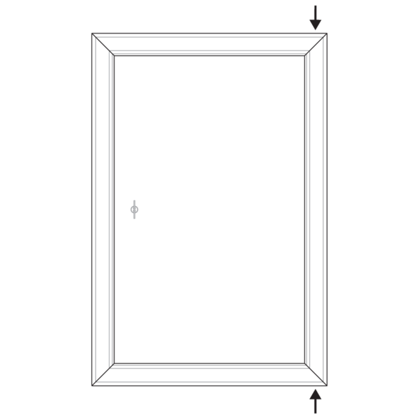
Unscrew the finishing cap from the opening in the door. Use the key to do this.
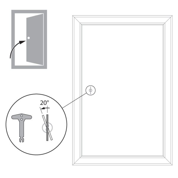
Turn the key 20° anti-clockwise and push the shutter into its open position.
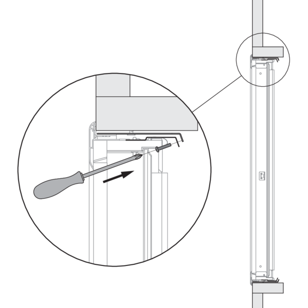
Operation: manual closing
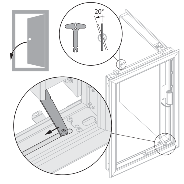
Turn the key 20° anti-clockwise. Push the actuating arm in the direction of the arrow and pull the shutter into its closed position.
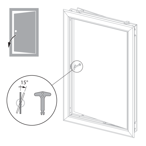
Turn the key 15° clockwise. The key blocks in the lock and the door can be pulled into its lock.
Electrical wiring
The electrical connection is possible via the 2 corners at the side of the hinges.
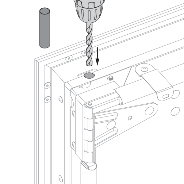
Drill a hole in the refractory material at the chosen corner(s). The galvanised part at the inside of the shutter is already indented.
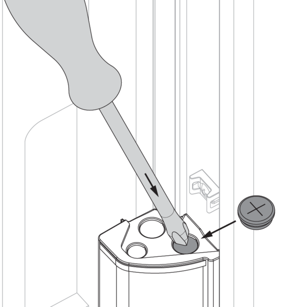
Pierce an opening in the connection box. Affix the grommet delivered with the product.
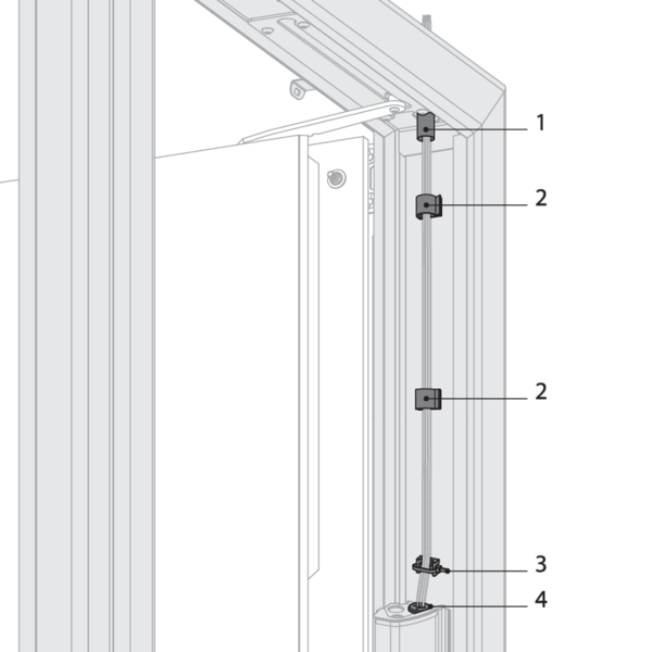
Lead the cables through the opening. Use the protective sleeve (1), the fixation clips (2) and the plastic cable clamp (3) to attach the cables to the frame. Lead the cables to the connection box through the grommet (4) and connect according to the electrical connection diagram.
Caution: after passing and fixing the cables, you need to seal the drilled hole in the refractory plates around the electrical cables with fire resistant adhesive sealant (BCM f.e.).
Caution: after passing and fixing the cables, you need to seal the drilled hole in the refractory plates around the electrical cables with fire resistant adhesive sealant (BCM f.e.).
Installation in a duct
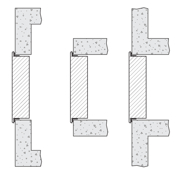
The shutter is fixed in the opening. It can be placed either in the duct, in the duct axis, outside the duct or duct extension or in surface-mounted.
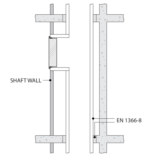
Example of installation in a shaft
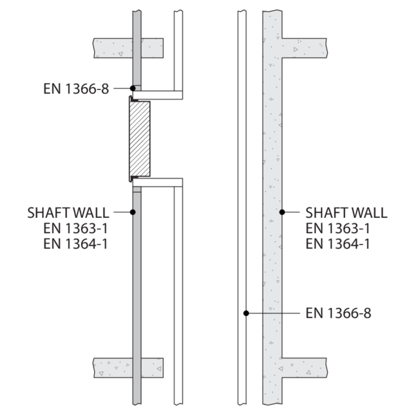
Example of installation in a shaft
Installation into vertical concrete shaft with mounting frame

Make an opening with dimensions (W+20) x (H+20) mm.
Mortaring the mounting frame is not permitted.
Mortaring the mounting frame is not permitted.
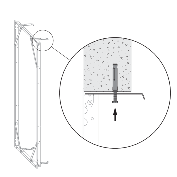
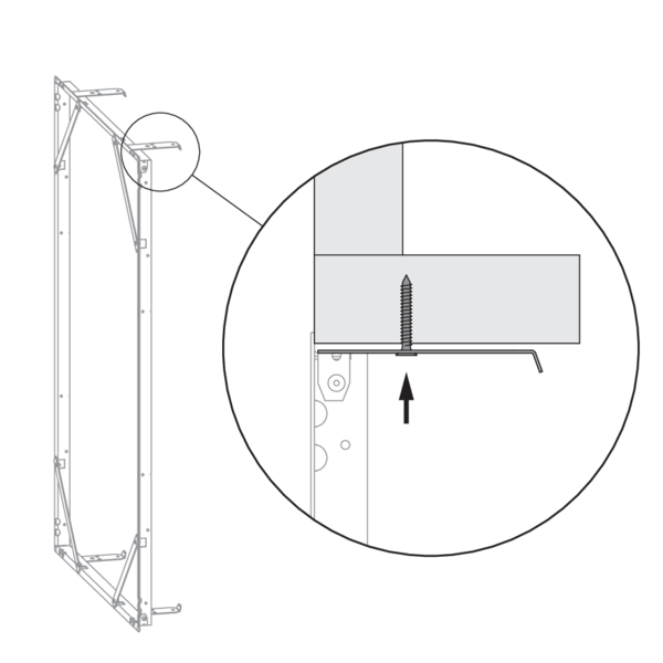
The mounting frame should always be fastened to the concrete duct with screws and dowels (Ø 6 x minimum 60 mm, steel or stainless steel).
Two fixing lugs are provided at the bottom and at the top of the mounting frame: fold these against the duct and fasten the mounting frame with 4 screws Ø 6 x 60 mm, taking care not to misshape it. These screws can be inserted through any of the punched holes in the lugs, depending on the thickness of the duct wall. The finished opening must have the same size as the mounting frame (W+10) x (H+10) mm.
Two fixing lugs are provided at the bottom and at the top of the mounting frame: fold these against the duct and fasten the mounting frame with 4 screws Ø 6 x 60 mm, taking care not to misshape it. These screws can be inserted through any of the punched holes in the lugs, depending on the thickness of the duct wall. The finished opening must have the same size as the mounting frame (W+10) x (H+10) mm.
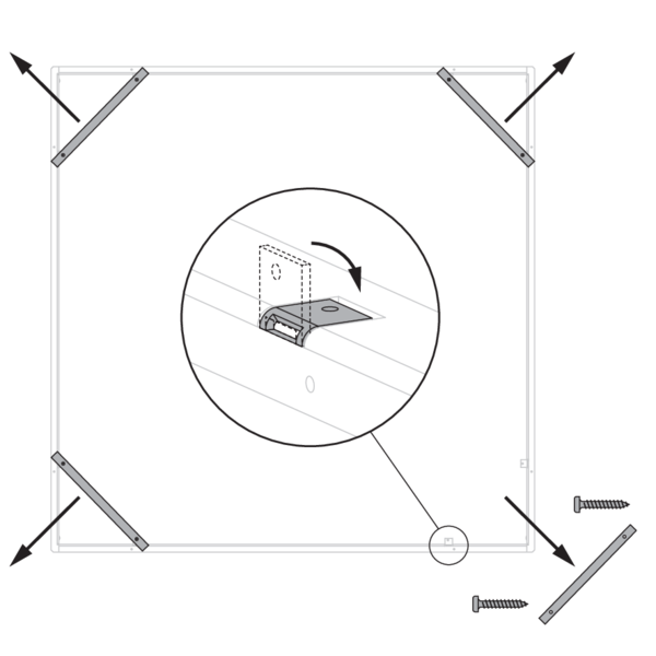
Put aside the screws that are affixed to one of the cross slats, then unscrew the 4 cross slats of the mounting frame and fold the 8 fastening plates in the frame.
When the EASY-KGC AP mounting frame is used, unfold the drop-guard grid (90°) in the duct.
When the EASY-KGC AP mounting frame is used, unfold the drop-guard grid (90°) in the duct.
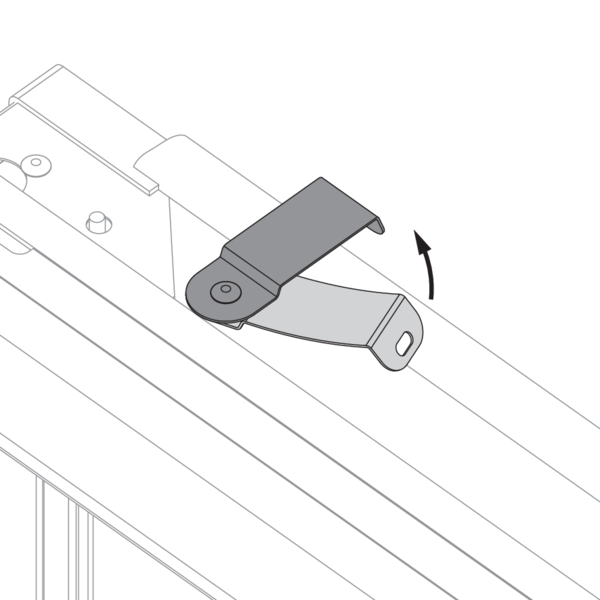
Rotate the four fastening plates on the damper 90° (to the upright position).

Open the shutter and position it in the mounting frame.
Fasten the shutter onto the mounting frame with the 4 screws supplied, as shown in the drawing. Tightening the screws pulls the shutter towards the wall until its final position. You can also slightly correct the angle of the shutter with respect to the mounting frame.
Connect the mechanism according to the wiring diagram.
Caution: Connecting the frame to an uneven surface can lead to distortion of this frame. Check whether the slack between the frame and the surface of the door is still acceptable.
Check the mobility of the shutter.

Tighten the postion screws until just against the shaft, without distorting the frame. These screws prevent the Kamouflage AP from sagging in the opening.
Installation into vertical concrete shaft without mounting frame
Rotate the four fastening plates on the damper 90° (to the upright position).
The fastening plates are not used for an installation without a mounting frame.
The fastening plates are not used for an installation without a mounting frame.

Make an opening with dimensions (W+10) x (H+10) mm.
Fix the shutter in the opening using 4 screws and dowels Ø6 x 60 mm.
Connect the mechanism according to the wiring diagram.
Check the mobility of the shutter.
Fix the shutter in the opening using 4 screws and dowels Ø6 x 60 mm.
Connect the mechanism according to the wiring diagram.
Check the mobility of the shutter.
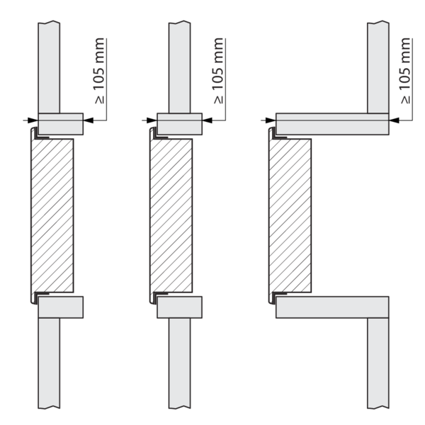
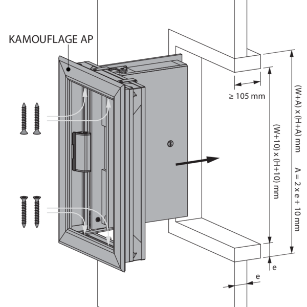
Installation into vertical duct with built-in mounting frame: general instructions for all types of ducts (other than concrete)
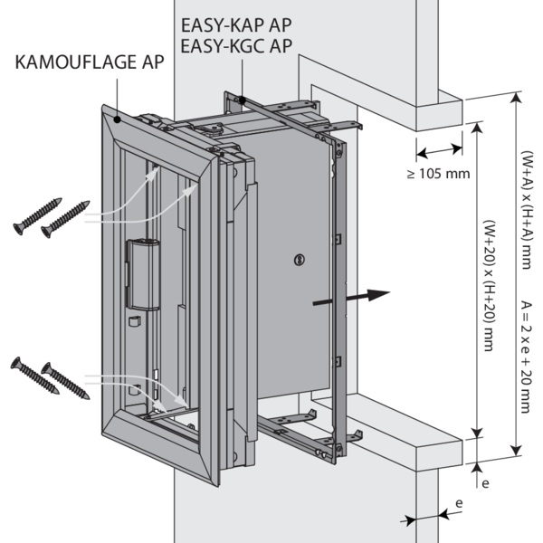
Make an opening with dimensions (W+A) x (H+A) mm. A = 2 x thickness sleeve (e) + 20 mm .
Fit a sleeve of the same type of material and thickness as the duct (thickness e) of minimum 105 mm deep in the opening.
Fit a sleeve of the same type of material and thickness as the duct (thickness e) of minimum 105 mm deep in the opening.
Two fixing lugs are provided at the bottom and at the top of the mounting frame: fold these against the sleeve.
Screw the mounting frame to the sleeve using screws Ø 6 x e mm (e-thickness of the sheet material). These screws can be fixed in one of the openings provided for this purpose, depending on the depth of the sleeve.
Take care not to misshape the frame during its installation. The finished opening must have the same size as the mounting frame (W+10) x (H+10) mm.
Take care not to misshape the frame during its installation. The finished opening must have the same size as the mounting frame (W+10) x (H+10) mm.
Put aside the screws that are affixed to one of the cross slats, then unscrew the 4 cross slats of the mounting frame and fold the 8 fastening plates in the frame.
When the EASY-KGC AP mounting frame is used, unfold the drop-guard grid (90°) in the duct.
When the EASY-KGC AP mounting frame is used, unfold the drop-guard grid (90°) in the duct.
Rotate the four fastening plates on the damper 90° (to the upright position).
Open the shutter and position it in the mounting frame.
Fasten the shutter onto the mounting frame with the 4 screws supplied, as shown in the drawing. Tightening the screws pulls the shutter towards the wall until its final position. You can also slightly correct the angle of the shutter with respect to the mounting frame.
Connect the mechanism according to the wiring diagram.
Caution: Connecting the frame to an uneven surface can lead to distortion of this frame. Check whether the slack between the frame and the surface of the door is still acceptable.
Check the mobility of the shutter.
Fasten the shutter onto the mounting frame with the 4 screws supplied, as shown in the drawing. Tightening the screws pulls the shutter towards the wall until its final position. You can also slightly correct the angle of the shutter with respect to the mounting frame.
Connect the mechanism according to the wiring diagram.
Caution: Connecting the frame to an uneven surface can lead to distortion of this frame. Check whether the slack between the frame and the surface of the door is still acceptable.
Check the mobility of the shutter.
Tighten the postion screws until just against the shaft, without distorting the frame. These screws prevent the Kamouflage AP from sagging in the opening.
Installation into vertical duct (without a mounting frame): general instructions for all types of ducts (other than concrete)
Rotate the four fastening plates on the damper 90° (to the upright position).
The fastening plates are not used for an installation without a mounting frame.
The fastening plates are not used for an installation without a mounting frame.
Make an opening with dimensions (W+A) x (H+A) mm. A = 2 x thickness sleeve (e) + 10 mm.
Fit a sleeve of the same type of material and thickness as the duct (thickness e) of minimum 105 mm deep in the opening.
Place the shutter in the opening.
Ensure the cables are not trapped at this stage.
Fix the shutter in the opening using 4 screws Ø6 x 40 mm.
Caution: make sure that the screws don't exceed the sleeve's thickness!
Connect the mechanism according to the wiring diagram.
Check the mobility of the shutter.

Example of mounting in a branch of a vertical duct, with a pre-wall finish.
Finishing
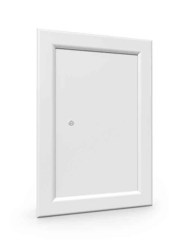
With the ATOUT RAL9010 option, the entire shutter receives a white lacquered finish (RAL 9010 matte).
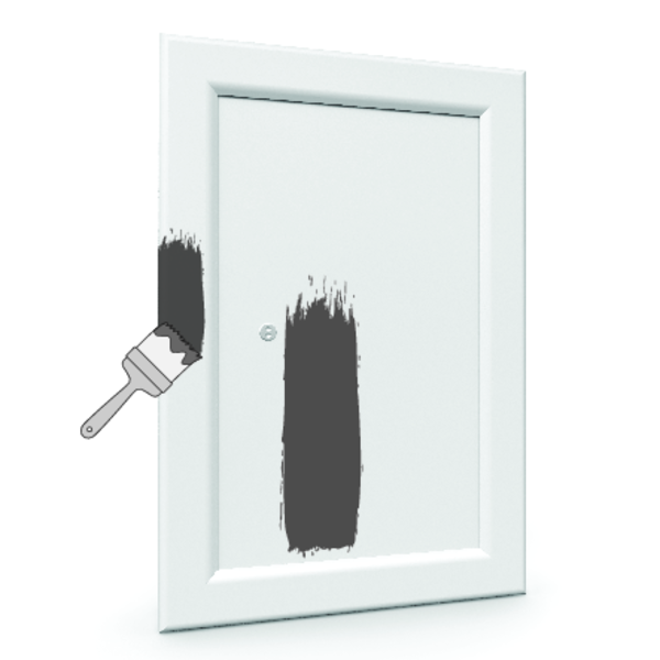
Finish of your choice: with acrylic paint or wallpaper.
Caution: don't fill / cover the joint between the covering plate and the aluminium profile in order to guarantee that the shutter can open.
Caution: don't fill / cover the joint between the covering plate and the aluminium profile in order to guarantee that the shutter can open.
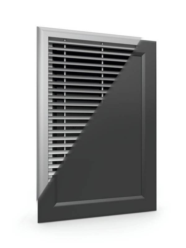
Option: BLACK. Only for use with grille. Option to have the shutter finished in black to reduce its visibility behind the grille.
General remarks
- The installation must comply with the installation manual and the classification report.
- The installation of the smoke control duct must comply with the classification report delivered by the manufacturer.
- Axis orientation: see the declaration of performance.
- Avoid the obstruction of adjoining smoke control ducts.
- Verify if the blade can move freely.
- Rf-t smoke dampers may be applied to smoke control ducts that have been tested according to EN 1366-8 and EN 1366-9 as appropriate.
- Caution: when fitting, the product should be handled with care and remain protected from any sealing products.
- Caution: before putting the installation into operation, clean off all the dust and dirt.
- Caution: bear in mind the blade’s clearance inside the smoke control duct.