CU-LT - Installation
Installation at a minimal distance from another damper or from an adjacent supporting construction
Principle
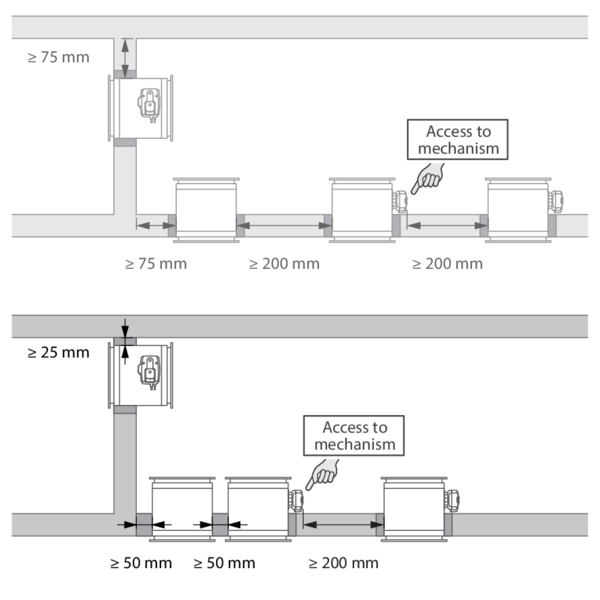
According to the European test standard EN 1366-2, a fire damper must be installed at a minimum distance of 75 mm from an adjacent supporting construction (wall/floor) and 200 mm from another damper, unless the solution was tested at a shorter distance. This range of Rf-t fire dampers has been successfully tested and can be installed in a vertical or horizontal supporting construction, at a distance below the minimum set by the standard.
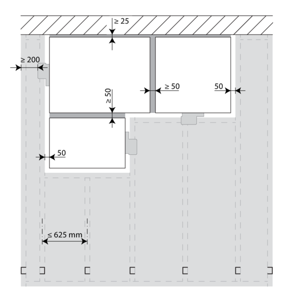
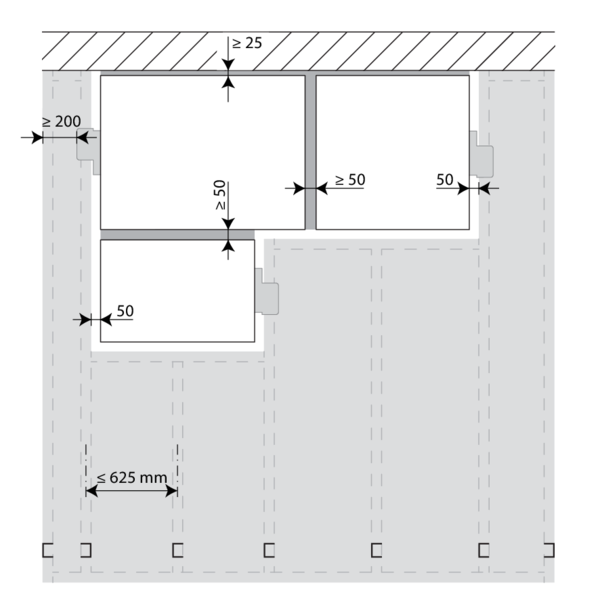
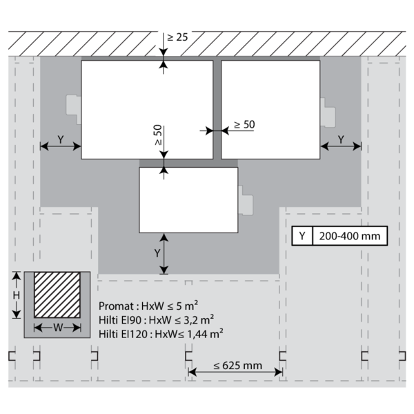
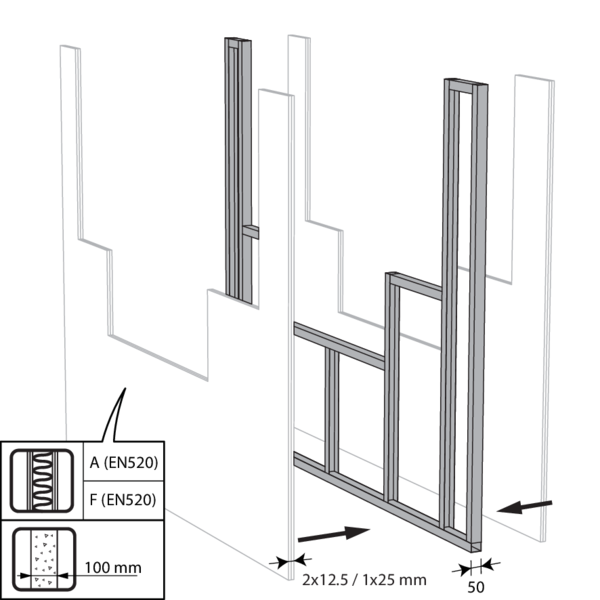
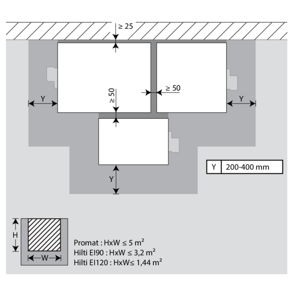
For rectangular dampers, the minimal distance is set to 50 mm between 2 dampers or between a damper and a vertical wall, and to 25 mm between a damper and a floor/ceiling.
According to the European test standard EN 1366-2, a fire damper must be installed at a minimum distance of 75 mm from an adjacent supporting construction (wall/floor) and 200 mm from another damper, unless the solution was tested at a shorter distance. This range of Rf-t fire dampers has been successfully tested and can be installed in a vertical or horizontal supporting construction, at a distance below the minimum set by the standard.
For rectangular dampers, the minimal distance is set to 50 mm between 2 dampers or between a damper and a vertical wall, and to 25 mm between a damper and a floor/ceiling.
Certified solution
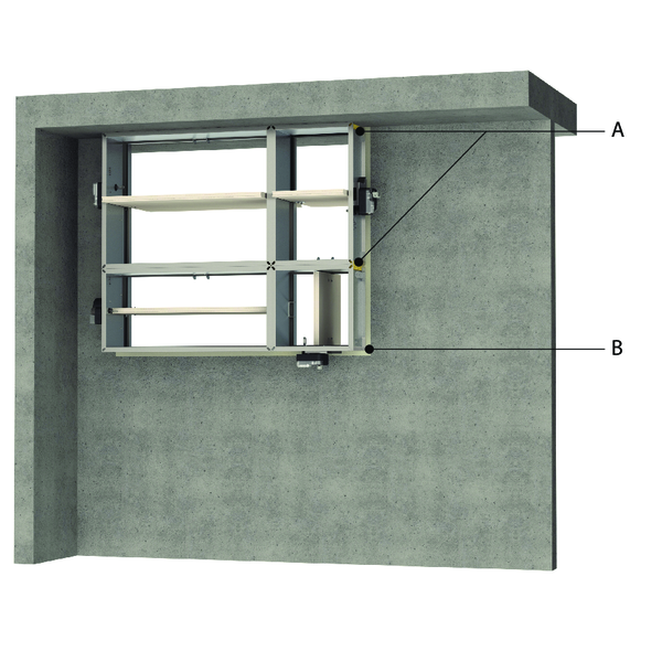
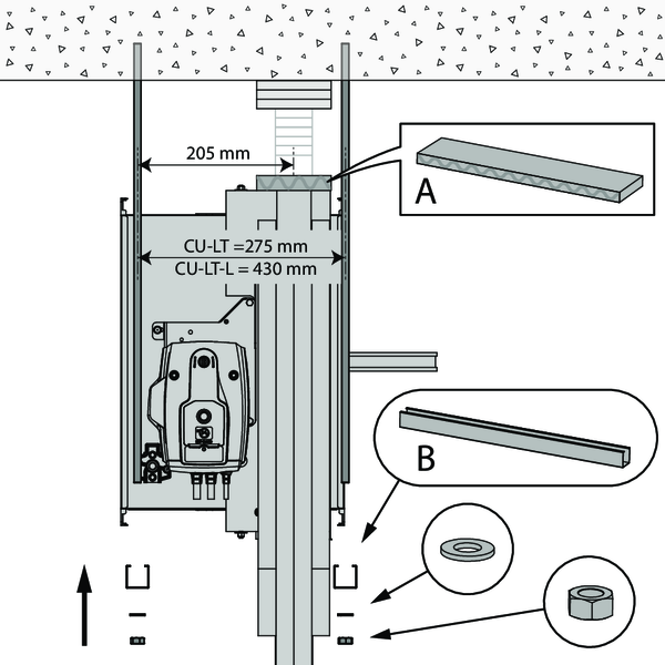
For the Rf-t fire dampers, the solution consists of the following elements: A: Universal sealing for minimal distance; B: Sealing compliant with existing classifications (Declaration of Performance).
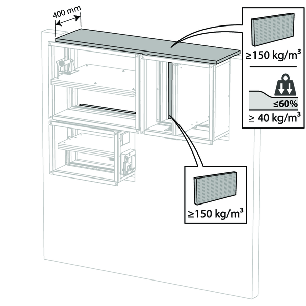
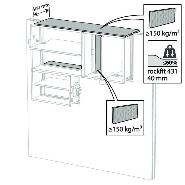
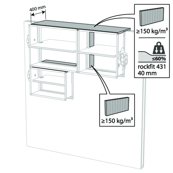
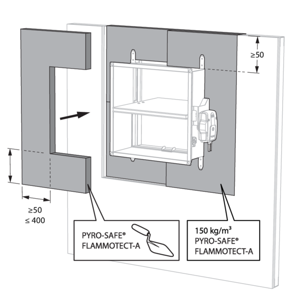
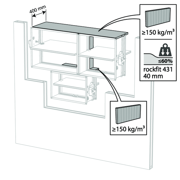
A. Sealing of the opening at the side with minimal distances between damper and wall/ceiling or another fire damper: rigid stone wool panels (150 kg/m³) are applied to a depth of min. 400 mm, of which 150 mm on the mechanism side of the wall. On the non-mechanism side of the wall, the stone wool panels must be at least flush with the wall.
This sealing is applied over the whole width/height of the damper(s).
When the damper is installed at a distance of 25 mm from a floor/ceiling, the rigid high-density stone wool panels (A) may be replaced with standard 40 kg/m³ stone wool, compressed by at least 40%.
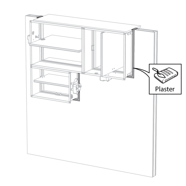
B. Sealing of the rest of the opening according to the existing classifications for the fire damper (Declaration of Performance).
Detailed information for each wall/sealing combination can be found in the respective installation methods.
The installer may choose the direction of the blade axis freely: horizontal or vertical axis.
For the Rf-t fire dampers, the solution consists of the following elements: A: Universal sealing for minimal distance; B: Sealing compliant with existing classifications (Declaration of Performance).
A. Sealing of the opening at the side with minimal distances between damper and wall/ceiling or another fire damper: rigid stone wool panels (150 kg/m³) are applied to a depth of min. 400 mm, of which 150 mm on the mechanism side of the wall. On the non-mechanism side of the wall, the stone wool panels must be at least flush with the wall.
This sealing is applied over the whole width/height of the damper(s).
When the damper is installed at a distance of 25 mm from a floor/ceiling, the rigid high-density stone wool panels (A) may be replaced with standard 40 kg/m³ stone wool, compressed by at least 40%.
B. Sealing of the rest of the opening according to the existing classifications for the fire damper (Declaration of Performance).
Detailed information for each wall/sealing combination can be found in the respective installation methods.
The installer may choose the direction of the blade axis freely: horizontal or vertical axis.
Restrictions
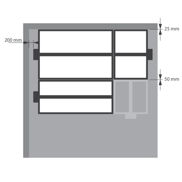
A maximum of 2 rectangular dampers can be installed at a minimum distance from one another, both vertically and horizontally (maximum cluster of 4 dampers).
Note: when sealing the opening with panels of fire resistant stone wool, the maximum number of dampers also depends on the maximum “blank seal” allowed for the selected sealing material. Please refer to the manufacturer's instructions for this information.
Note: separate conditions apply for installation in flexible shaftwall and CLT wall. Detailed information can be found in the relevant installation methods.
Installation in rigid wall and floor
The product was tested and approved in:
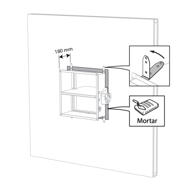
- Aerated concrete ≥ 100 mm | EI 90 (ve i o) S - (500 Pa) | Mortar | Type of installation: built-in 0/90/180/270°. Minimal distances authorised. | 200x100 mm ≤ CU-LT ≤ 800x600 mm
- Aerated concrete ≥ 100 mm | EI 120 (ve i o) S - (500 Pa) | Gypsum | Type of installation: built-in 0/90/180/270°. Minimal distances authorised. | 200x100 mm ≤ CU-LT ≤ 800x600 mm
- Reinforced concrete ≥ 110 mm | EI 90 (ho i o) S - (500 Pa) | Mortar | Type of installation: built-in 0/90/180/270°. Minimal distances authorised. | 200x100 mm ≤ CU-LT ≤ 800x600 mm
- Reinforced concrete ≥ 150 mm | EI 120 (ho i o) S - (500 Pa) | Gypsum | Type of installation: built-in 0/90/180/270°. Minimal distances authorised. | 200x100 mm ≤ CU-LT ≤ 800x600 mm
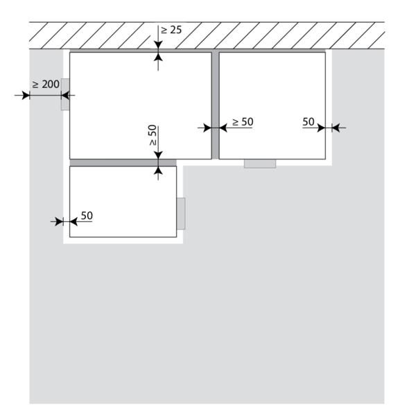
The dampers can be installed at a minimum distance from an adjacent floor/ceiling (≥ 25 mm), from an adjacent wall or from another damper (≥ 50 mm).
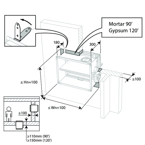
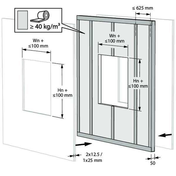
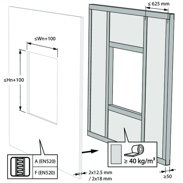
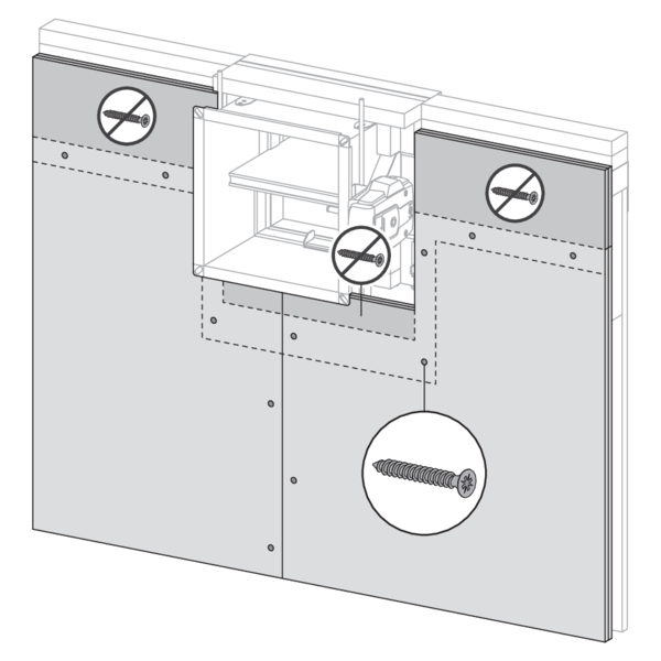
Make the necessary openings (Wn + 100 mm) x (Hn + 100 mm) in the wall.
Mount the dampers in the opening.
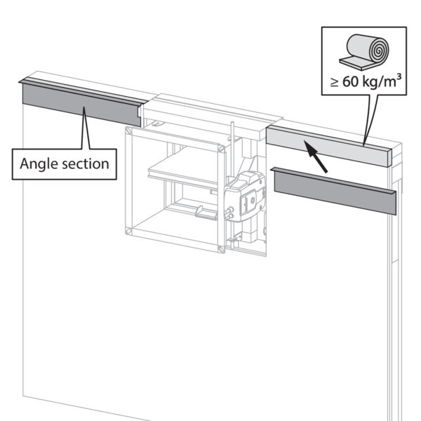
Apply rigid stone wool panels (≥ 150 kg/m³) to a depth of 400 mm (150 mm on the mechanism side of the wall) to seal the opening at the side with minimal distances.
This sealing is applied over the whole width/height of the damper(s).
When the damper is installed at a distance of 25 mm from a floor/ceiling, the rigid high-density stone wool panels may be replaced with standard ≥ 40 kg/m³ stone wool (e.g. Rockfit 431), compressed by at least 40%.
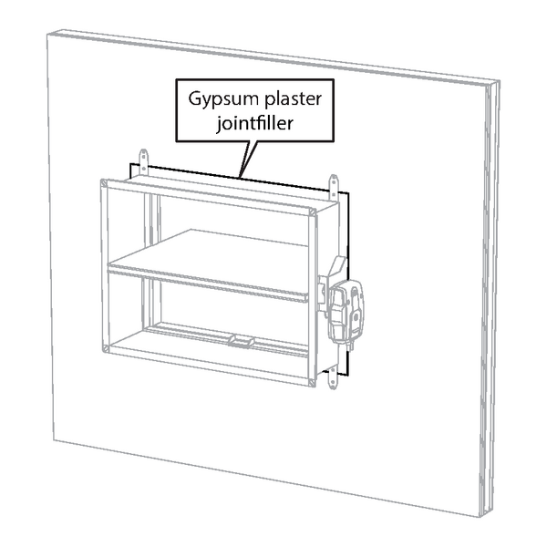
Seal the rest of the opening with standard mortar or gypsum.
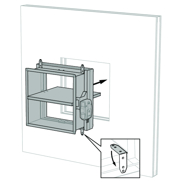
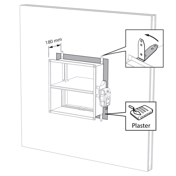
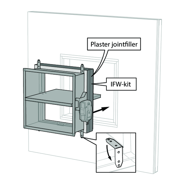
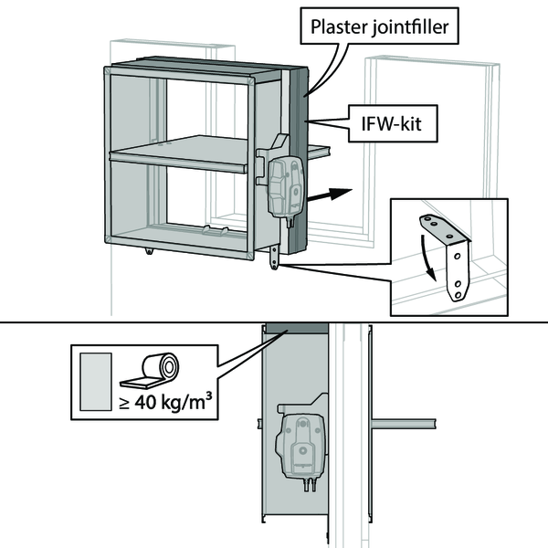
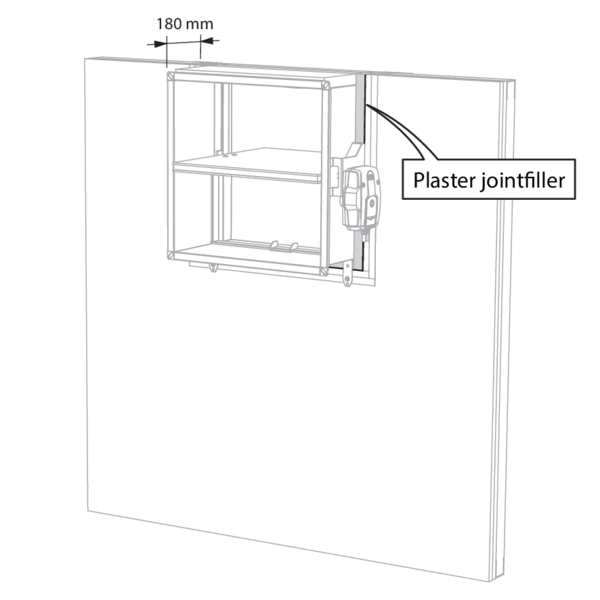
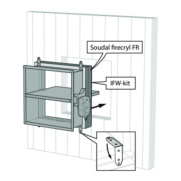
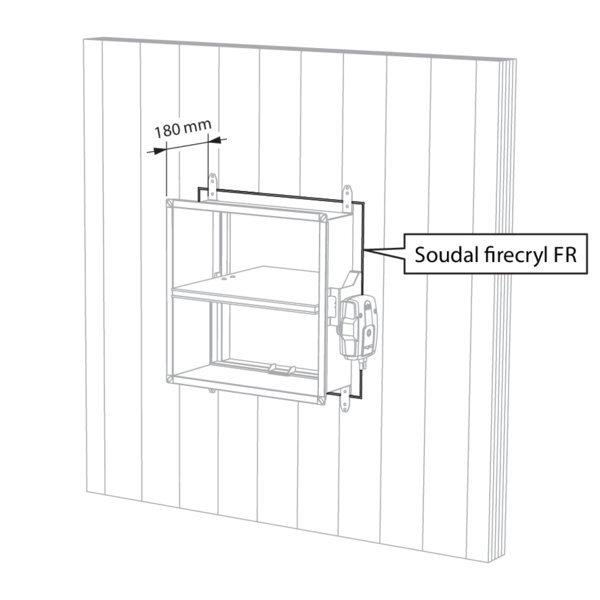
Installation in rigid wall with IFW installation block
The product was tested and approved in:
- Aerated concrete ≥ 105 mm | EI 90 (ve i o) S - (300 Pa) | Installation block IFW | Type of installation: built-in 0/90/180/270°. Minimal distances authorised. | 200x100 mm ≤ CU-LT ≤ 800x600 mm
- Aerated concrete ≥ 100 mm | EI 90 (ve i o) S - (500 Pa) | Installation block IFW | Type of installation: built-in 0/90/180/270° | 200x100 mm ≤ CU-LT ≤ 800x600 mm
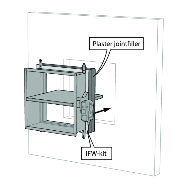
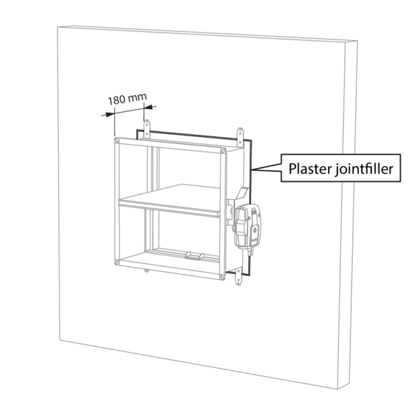
If the wall is ≥ 105 mm thick, the fire damper may be placed at minimum distance from the ceiling/floor slab.

If the wall is ≥ 105 mm thick, the fire dampers may be placed at a minimum distance from each other and from the ceiling/floor slab.
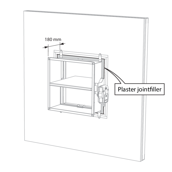
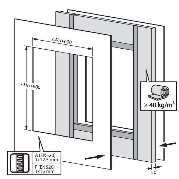
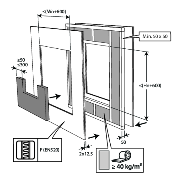
Installation in flexible wall (metal stud and plasterboard) with IFW installation block
The product was tested and approved in:
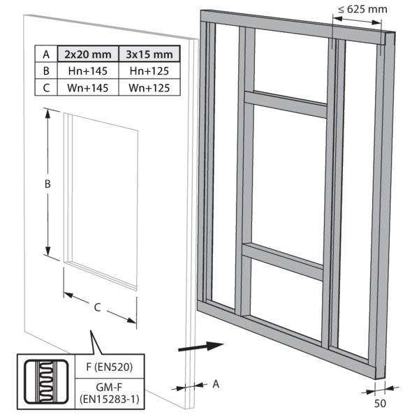
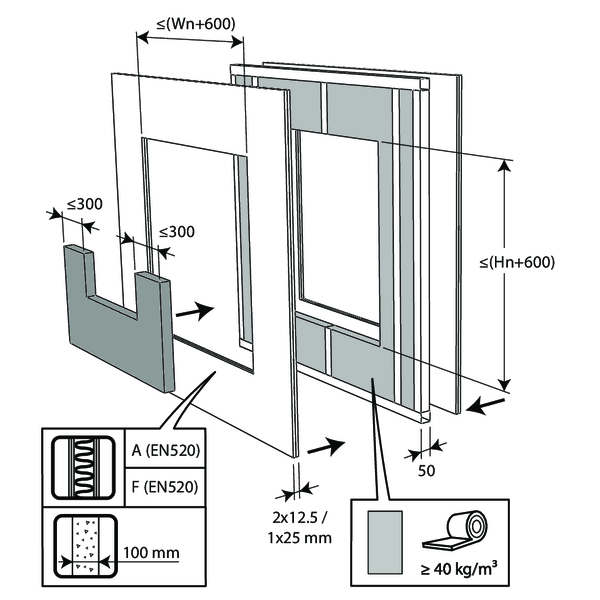
- Metal studs gypsum plasterboard Type A (EN 520) ≥ 100 mm | EI 60 (ve i o) S - (500 Pa) | Installation block IFW | Type of installation: built-in 0/90/180/270° | 200x100 mm ≤ CU-LT ≤ 800x600 mm
- Metal studs gypsum plasterboard Type F (EN 520) ≥ 100 mm | EI 90 (ve i o) S - (500 Pa) | Installation block IFW | Type of installation: built-in 0/90/180/270° | 200x100 mm ≤ CU-LT ≤ 800x600 mm
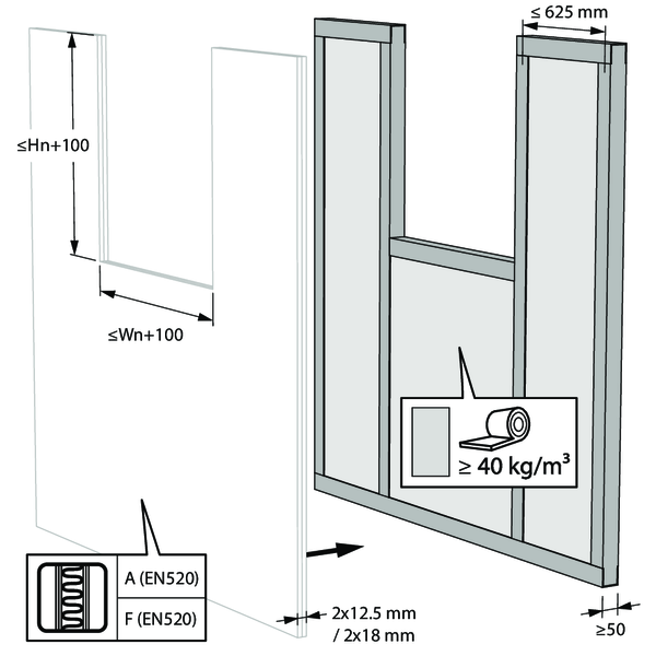
Installation in flexible wall - metal stud and gypsum
The product was tested and approved in:
- Metal studs gypsum plasterboard Type A (EN 520) ≥ 100 mm | EI 60 (ve i o) S - (500 Pa) | Gypsum | Type of installation: built-in 0/90/180/270°. Minimal distances authorised. | 200x100 mm ≤ CU-LT ≤ 800x600 mm
- Metal studs gypsum plasterboard Type F (EN 520) ≥ 100 mm | EI 90 (ve i o) S - (500 Pa) | Gypsum | Type of installation: built-in 0/90/180/270°. Minimal distances authorised. | 200x100 mm ≤ CU-LT ≤ 800x600 mm
The dampers can be installed at a minimum distance from an adjacent floor/ceiling (≥ 25 mm), from an adjacent wall or from another damper (≥ 50 mm).

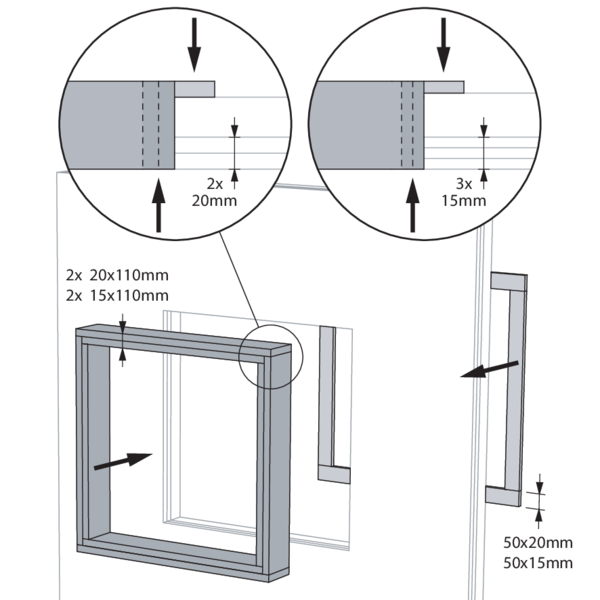
Build the drywall and mount horizontal and vertical studs around the opening.
When installing a single fire damper at a minimum distance from the ceiling, it is not necessary, from a fire technical point of view, to provide studs around the opening.
When installing a single fire damper at a minimum distance from the ceiling, it is not necessary, from a fire technical point of view, to provide studs around the opening.
Mount the dampers in the opening.
Apply rigid stone wool panels (≥ 150 kg/m³) to a depth of 400 mm (150 mm on the mechanism side of the wall) to seal the opening at the side with minimal distances.
This sealing is applied over the whole width/height of the damper(s).
When the damper is installed at a distance of 25 mm from a floor/ceiling, the rigid high-density stone wool panels may be replaced with standard ≥ 40 kg/m³ stone wool (e.g. Rockfit 431), compressed by at least 40%.
Seal the rest of the opening (50 mm) with standard gypsum across the entire wall thickness.
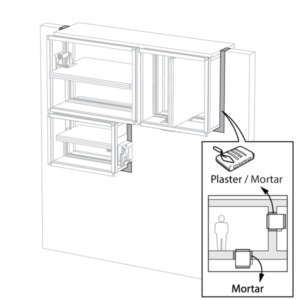
Installation in flexible wall - metal stud and mortar
The product was tested and approved in:
- Metal studs gypsum plasterboard Type A (EN 520) ≥ 100 mm | EI 60 (ve i o) S - (300 Pa) | Mortar | Type of installation: built-in 0/180°. Minimal distances authorised. | 200x100 mm ≤ CU-LT ≤ 800x600 mm
- Metal studs gypsum plasterboard Type F (EN 520) ≥ 100 mm | EI 90 (ve i o) S - (300 Pa) | Mortar | Type of installation: built-in 0/180°. Minimal distances authorised. | 200x100 mm ≤ CU-LT ≤ 800x600 mm

.png)
The dampers can be installed at a minimum distance from an adjacent floor/ceiling (≥ 25 mm), from an adjacent wall or from another damper (≥ 50 mm).
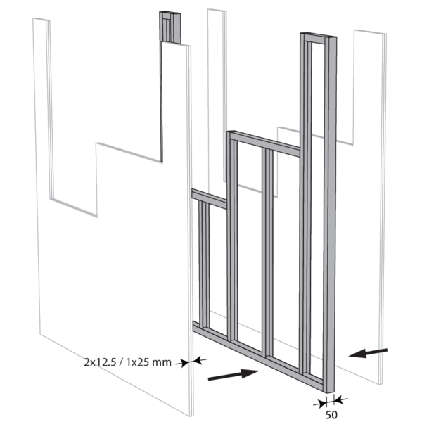
Build the drywall and mount horizontal and vertical studs around the opening.
When installing a single fire damper at a minimum distance from the ceiling, it is not necessary, from a fire technical point of view, to provide studs around the opening.
When installing a single fire damper at a minimum distance from the ceiling, it is not necessary, from a fire technical point of view, to provide studs around the opening.
Mount the dampers in the opening.
Apply rigid stone wool panels (≥ 150 kg/m³) to a depth of 400 mm (150 mm on the mechanism side of the wall) to seal the opening at the side with minimal distances.
This sealing is applied over the whole width/height of the damper(s).
When the damper is installed at a distance of 25 mm from a floor/ceiling, the rigid high-density stone wool panels may be replaced with standard ≥ 40 kg/m³ stone wool (e.g. Rockfit 431), compressed by at least 40%.
Apply rigid stone wool panels (≥ 150 kg/m³) to a depth of 400 mm (150 mm on the mechanism side of the wall) to seal the opening at the side with minimal distances.
This sealing is applied over the whole width/height of the damper(s).
When the damper is installed at a distance of 25 mm from a floor/ceiling, the rigid high-density stone wool panels may be replaced with standard ≥ 40 kg/m³ stone wool (e.g. Rockfit 431), compressed by at least 40%.
Seal the rest of the opening (50 mm) with standard mortar across the entire wall thickness.
Installation in flexible wall with deflection head (GDA)
The product was tested and approved in:
- Metal studs gypsum plasterboard Type F (EN 520) ≥ 100 mm | EI 120 (ve i o) S - (300 Pa) | Deflection head (GDA) + stone wool ≥ 40 kg/m³ | Type of installation: built-in 0/180° | 200x100 mm ≤ CU-LT + GDA ≤ 800x600 mm
Interrupt the deflection head (C) of the wall (the deflection head arrangement (C) can divert from the detail shown, please refer to the details of the wall system supplier).
Add gypsum plasterboards to reach 5 layers of 12.5 mm (or a total of 62.5 mm) on both sides of the fire damper (D). Leave an opening of Wn + 120 mm to accommodate the fire damper.
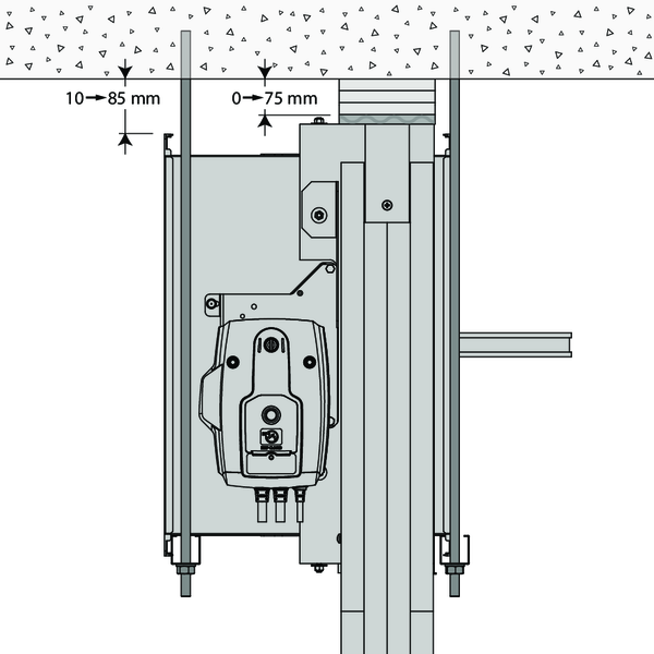
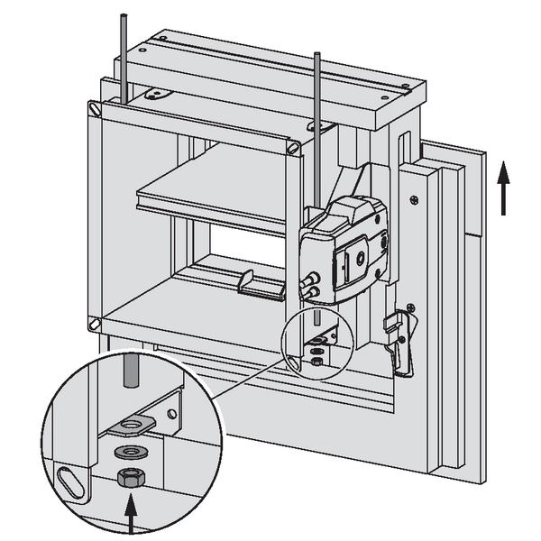
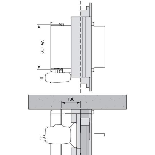
Attach 4 threaded rods (diameter ≥ 8 mm) to the ceiling at a distance of Wn + 10 mm. The distance between the rods and the wall is mentioned in picture 4.
If the fire damper with GDA is to be mounted at a distance from the ceiling, add layers of fire-resistant gypsum plasterboards (type F) to reach a maximum distance of 75 mm from the ceiling: ‘E’ boards in the opening, with a depth of 100 mm, and ‘F’ boards in the remaining width of the opening, with a depth of 50 mm.
Place a strip of stone wool (40 kg/m³) ‘A’ with dimensions 40 x 100 x (Wn + 120) mm on top of the GDA. Suspend the fire damper to the rods that hang from the ceiling by means of nuts and U-shaped suspension profiles (B).
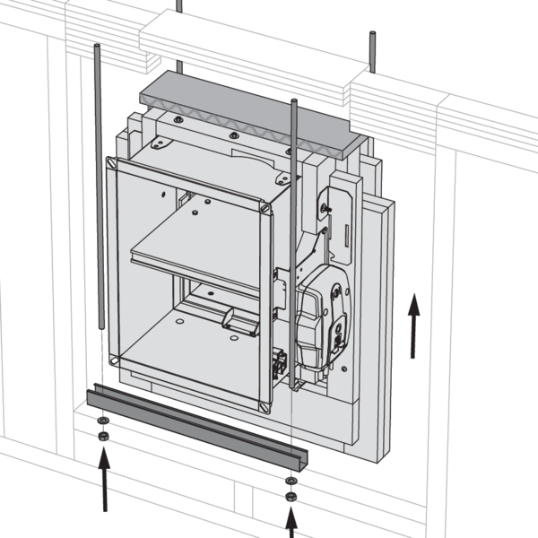
Tighten the nuts to move the GDA into position.
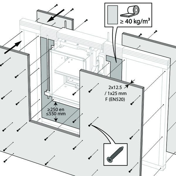
Size the gypsum plasterboards to overlap the flange of the GDA and fasten them with screws to the flange on 3 sides of the GDA. Fasten the plasterboards to the wall with screws, in compliance with the specifications of the wall system supplier.
Use the sealing material specified by the wall manufacturer to seal the connection between the fire damper and the wall.
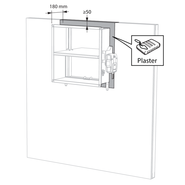
Installation in shaftwall, sealing with gypsum
The product was tested and approved in:
- Metal studs gypsum plasterboard Type A (EN 520) ≥ 75 mm | EI 30 (ve i o) S - (500 Pa) | Gypsum | Type of installation: built-in 0/90/180/270°. Minimal distances authorised. | 200x100 mm ≤ CU-LT ≤ 800x600 mm
The dampers can be installed at a minimum distance (≥ 50 mm) from a ceiling or floor slab.
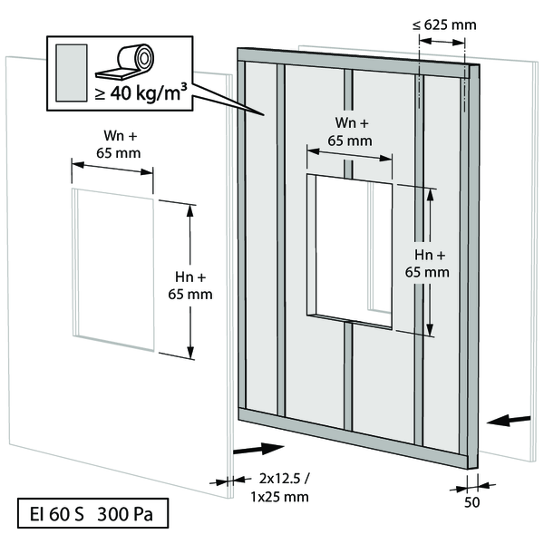
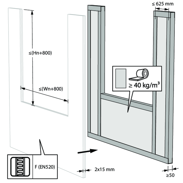
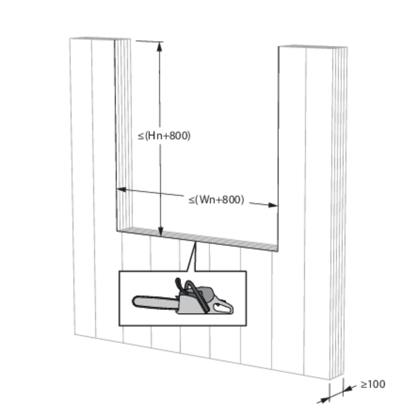
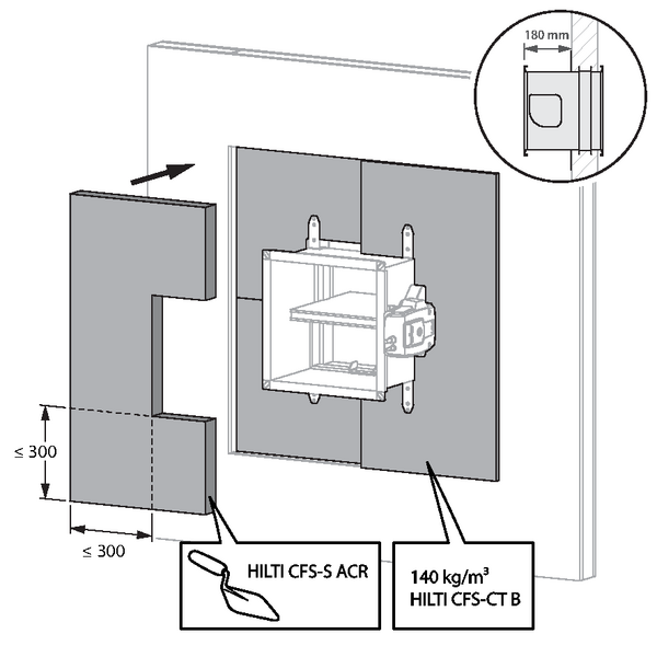
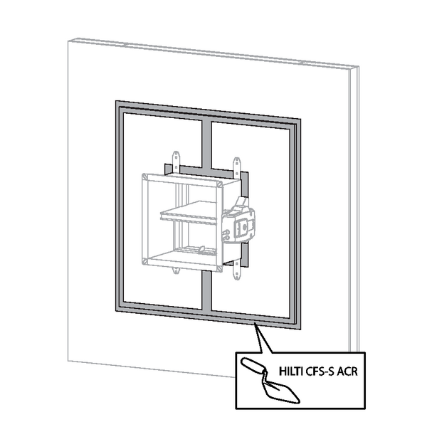
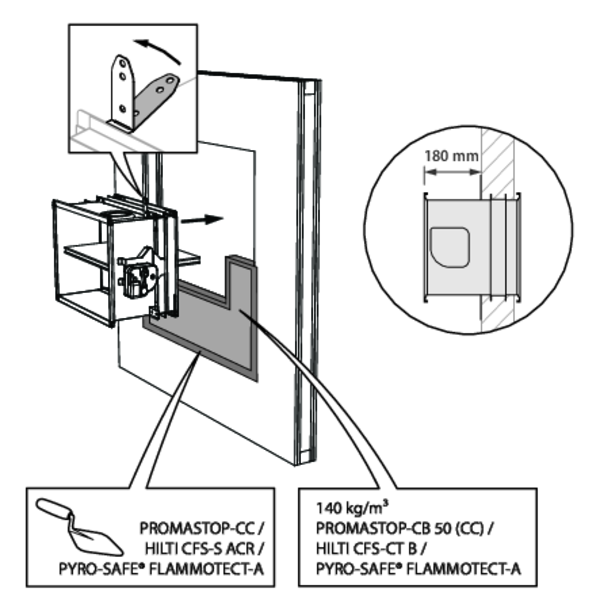
Installation in shaftwall, sealing with rigid stone wool boards with coating - EI 30 S
The product was tested and approved in:
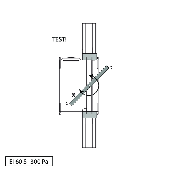
- Metal studs gypsum plasterboard Type F (EN 520) ≥ 75 mm | EI 30 (ve i o) S - (300 Pa) | Stone wool + coating ≥ 140 kg/m³ | Type of installation: built-in 0/90/180/270°. Minimal distances authorised. | 200x100 mm ≤ CU-LT ≤ 800x600 mm
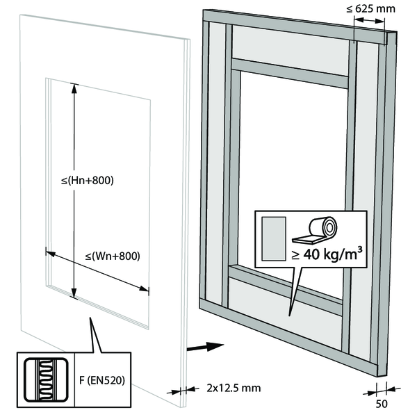
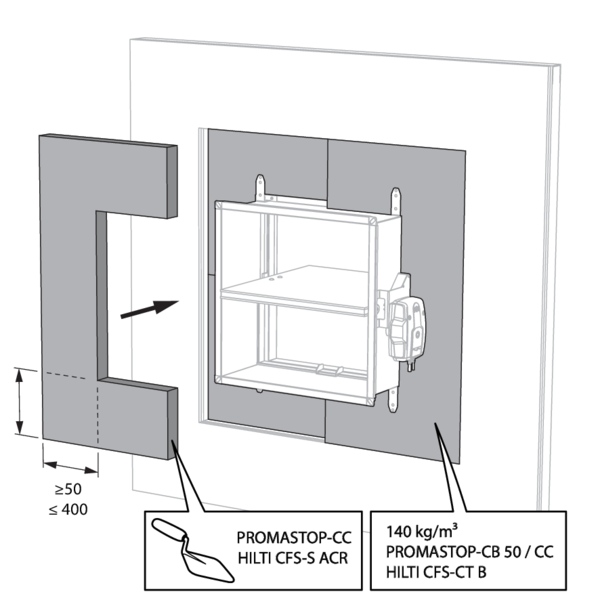
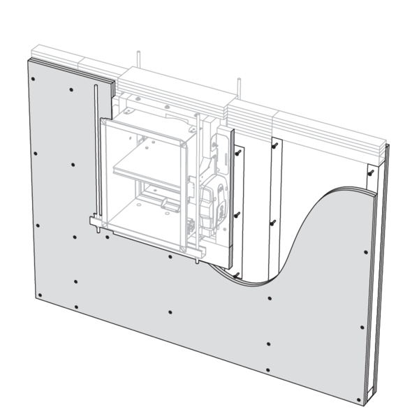
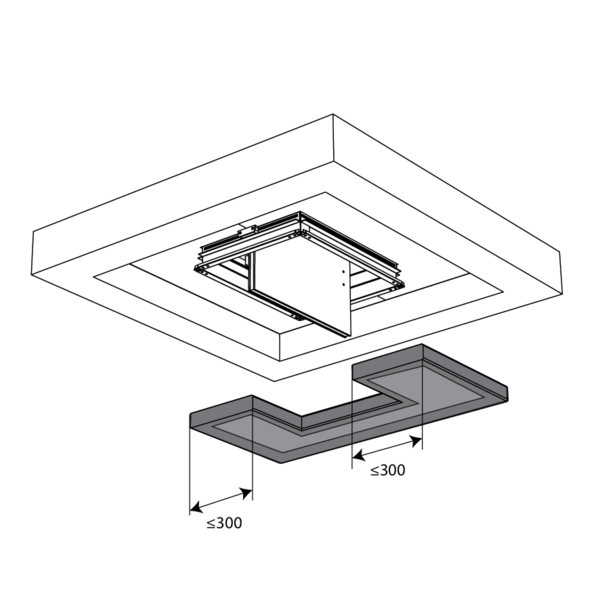
The opening around the damper is sealed with 2 rigid stone wool boards of 50 mm. These boards should be placed in a slanted position and the joints should be covered all around with filling paste.
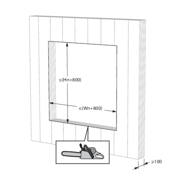
The damper does not need to be centered in the opening (with max dimensions Wn x Hn fire damper + 800 mm). The maximal distance between the damper and the edge of the opening is 400 mm.

The dampers can be installed at a minimum distance (≥ 50 mm) from a ceiling or floor slab.

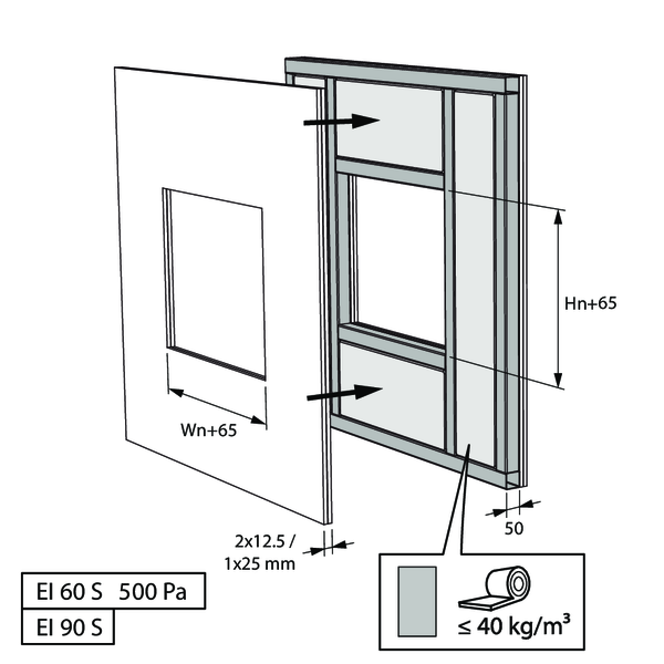
Installation in shaftwall, sealing with rigid stone wool boards with coating - EI 60 S
The product was tested and approved in:
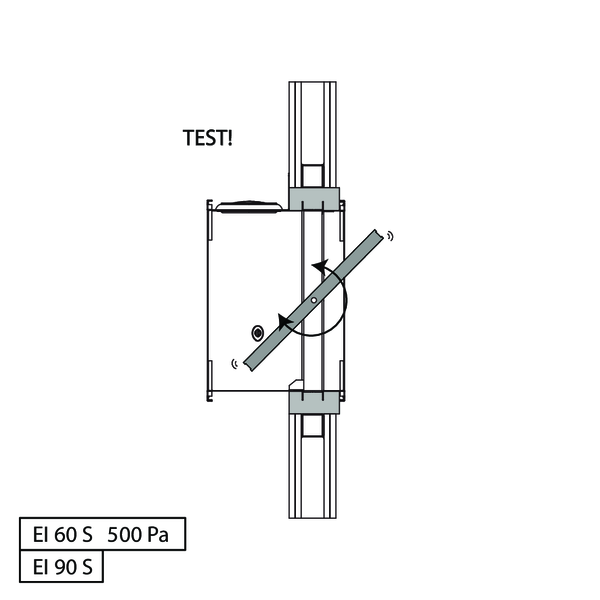
- Metal studs gypsum plasterboard Type F (EN 520) ≥ 80 mm | EI 60 (ve i o) S - (300 Pa) | Stone wool + coating ≥ 150 kg/m³ | Type of installation: built-in 0/180°. Minimal distances authorised. | 200x100 mm ≤ CU-LT ≤ 800x600 mm


The opening around the damper is sealed with 2 rigid stone wool boards of 50 mm. These boards should be placed in a slanted position and the joints should be covered all around with filling paste.

The damper does not need to be centered in the opening (with max dimensions Wn x Hn fire damper + 800 mm). The maximal distance between the damper and the edge of the opening is 400 mm.

Up to two fire dampers may be installed at a shorter distance from a floor/ceiling (≥ 50 mm) or from another damper (≥ 100 mm).
The opening around the damper (when installed at a shorter distance, also between damper and floor/ceiling and between max. 2 fire dampers) is sealed with 2 rigid stone wool boards of 50 mm. These boards should be placed in a slanted position and the joints should be covered all around with filling paste.
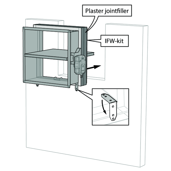
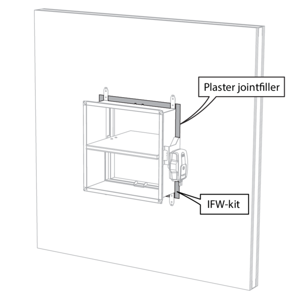
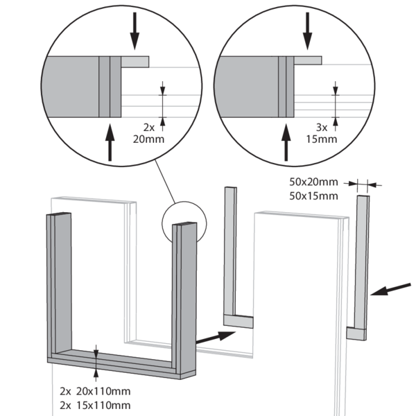
Installation in flexible shaftwall with IFW installation block
The product was tested and approved in:
- Metal studs gypsum plasterboard Type F (EN 520) ≥ 90 mm | EI 90 (ve i o) S - (300 Pa) | Installation block IFW | Type of installation: built-in 0/90/180/270°. Minimal distances authorised. | 200x100 mm ≤ CU-LT ≤ 800x600 mm
Depending on the shaftwall system, the cladding is 15 or 20mm thick.
Suitable for installation in shaftwalls with cementitious fibreboards and calcium silicate boards.
See manufacturer's instructions for EI90 walls.
Suitable for installation in shaftwalls with cementitious fibreboards and calcium silicate boards.
See manufacturer's instructions for EI90 walls.
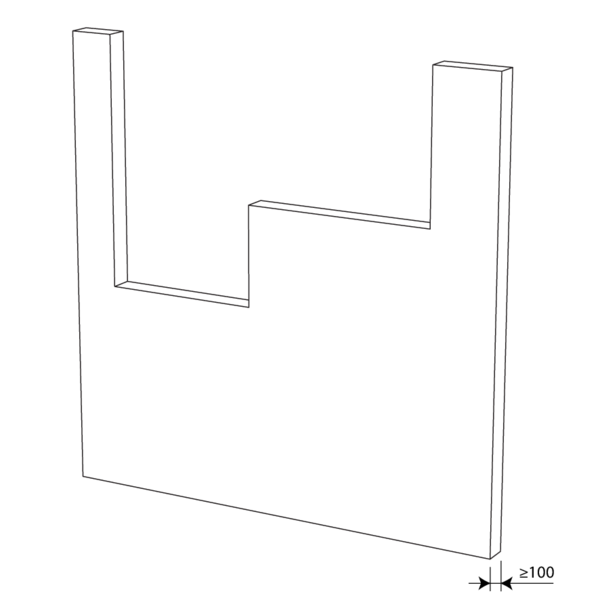
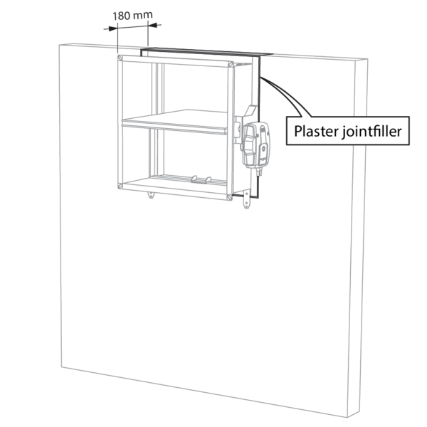
Alternatively, the aperture framing can also be stepped.
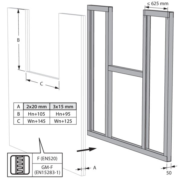
The fire damper may be placed at minimum distance from the ceiling/floor slab.
Alternatively, the aperture framing can also be stepped.
Fill the gap between the top of the damper and the floor slab with mineral wool.
The fire dampers may be placed at minimum distance from each other and from the ceiling/floor slab.
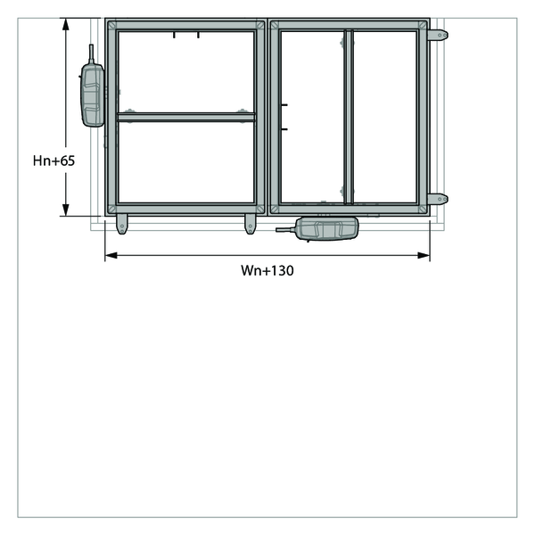
Installation in shaftwall, built according to British Gypsum construction details, 4-sided opening
The product was tested and approved in:
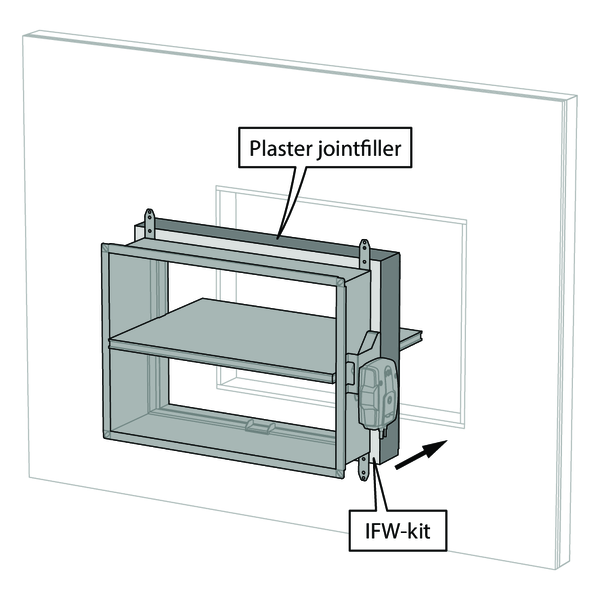
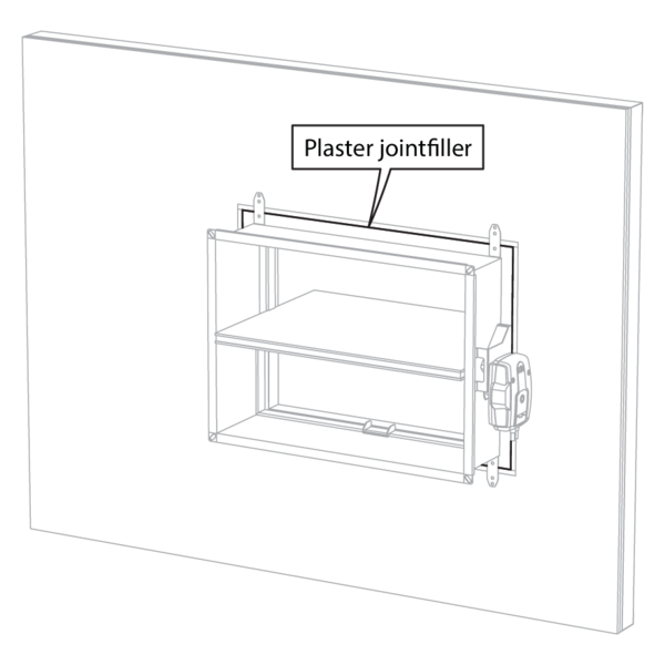
- Metal studs gypsum plasterboard Type F + Coreboard (EN 520) ≥ 85 mm | EI 60 (ve i o) S - (300 Pa) | Installation block IFW | Type of installation: built-in 0/180° | 200x100 mm ≤ CU-LT ≤ 800x600 mm
- Metal studs gypsum plasterboard Type F + Coreboard (EN 520) ≥ 90 mm | EI 90 (ve i o) S - (300 Pa) | Installation block IFW | Type of installation: built-in 0/180° | 200x100 mm ≤ CU-LT ≤ 800x600 mm
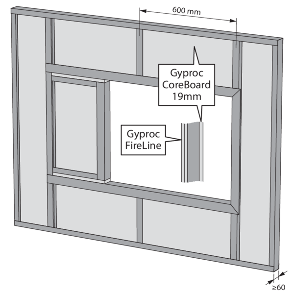
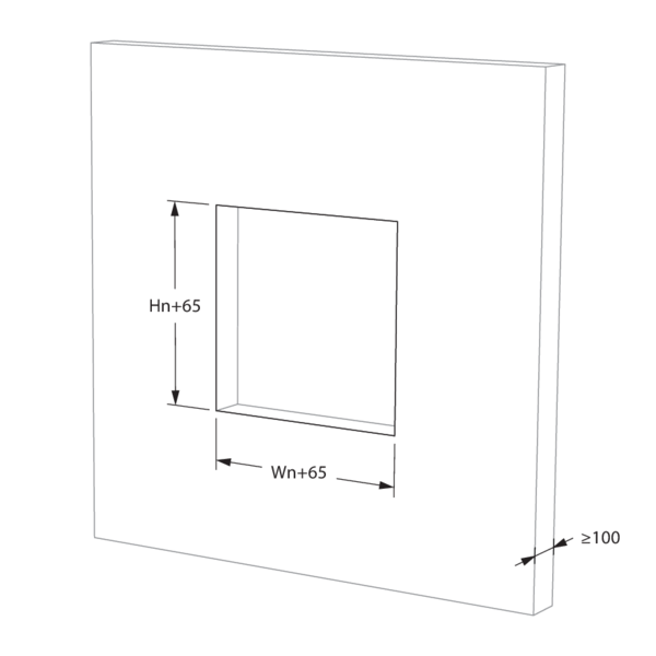
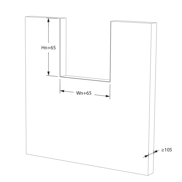
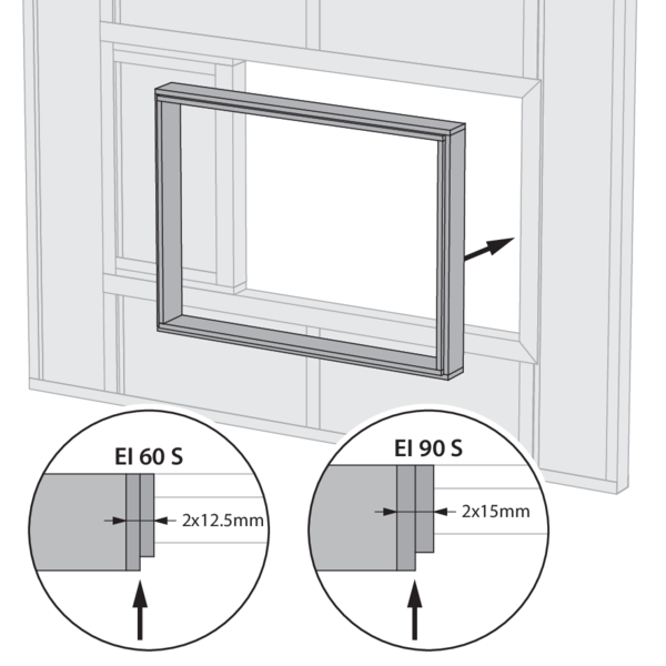
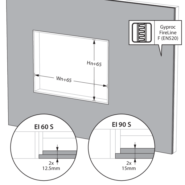
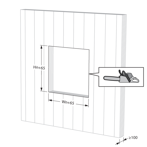
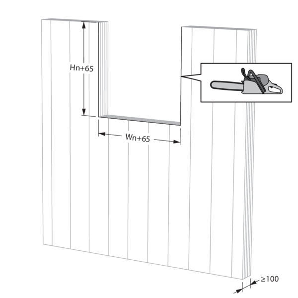
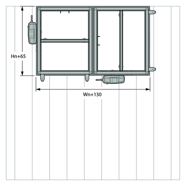
Build the shaftwall acc. to British Gypsum construction details. Create the opening in the wall between the studs or by bridging studs. Mind tolerances in the thickness of the British Gypsum Fireline boards when dimensioning the wall opening. Finished wall opening incl. lining to measure (Wn+65) x (Hn+65).
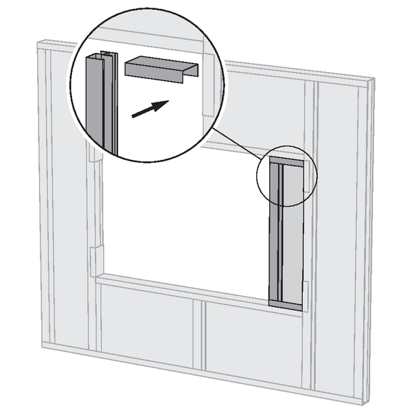
Installation in shaftwall, built according to Knauf construction details, 4-sided opening
The product was tested and approved in:
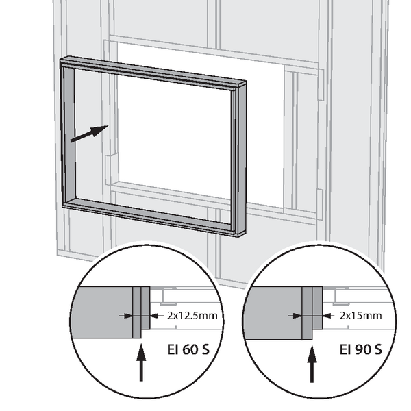
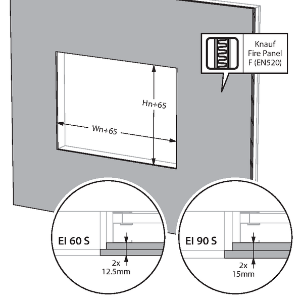
- Metal studs gypsum plasterboard Type F + Coreboard (EN 520) ≥ 85 mm | EI 60 (ve i o) S - (300 Pa) | Installation block IFW | Type of installation: built-in 0/180° | 200x100 mm ≤ CU-LT ≤ 800x600 mm
- Metal studs gypsum plasterboard Type F + Coreboard (EN 520) ≥ 90 mm | EI 90 (ve i o) S - (300 Pa) | Installation block IFW | Type of installation: built-in 0/180° | 200x100 mm ≤ CU-LT ≤ 800x600 mm
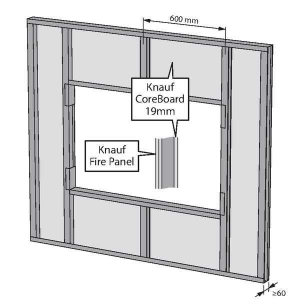
Build the shaftwall according to Knauf construction details. Create the opening in the wall between the studs or by bridging studs. Mind tolerances in the thickness of the Knauf Fire Panel boards when dimensioning the wall opening. Finished wall opening incl. lining to measure (Wn+65) x (Hn+65).

Installation in shaftwall, built according to Knauf construction details, 3-sided opening
The product was tested and approved in:
- Metal studs gypsum plasterboard Type F + Coreboard (EN 520) ≥ 85 mm | EI 60 (ve i o) S - (300 Pa) | Deflection head (DH) | Type of installation: built-in 0/180° | 200x150 mm ≤ CU-LT ≤ 800x600 mm
- Metal studs gypsum plasterboard Type F + Coreboard (EN 520) ≥ 90 mm | EI 90 (ve i o) S - (300 Pa) | Deflection head (DH) | Type of installation: built-in 0/180° | 200x150 mm ≤ CU-LT ≤ 800x600 mm
Position and fix the damper with option DH directly to the slab.
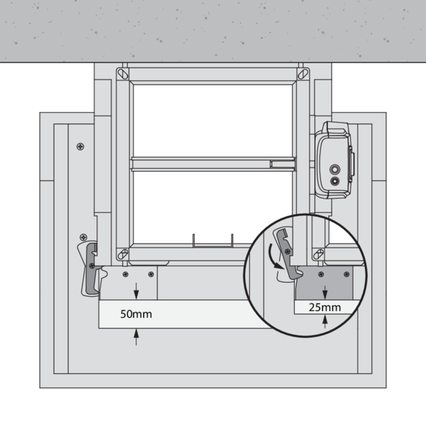
Set the correct deflection head range using the locks: 25 or 50 mm.
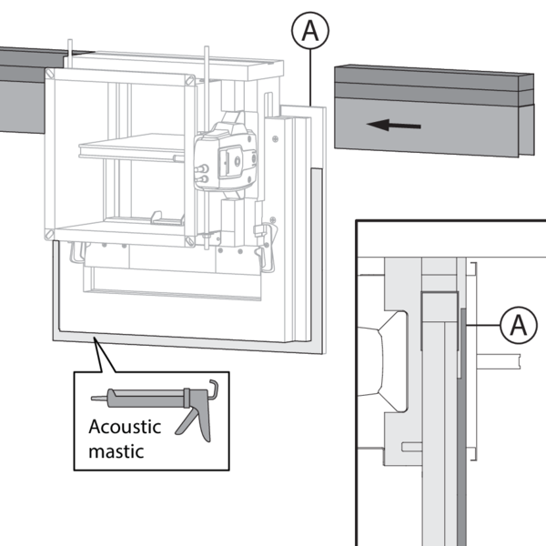
Install the top track of the partition. Slide the track into the groove opening towards the damper. Apply acoustic mastic on the outer face of the DH installation block.
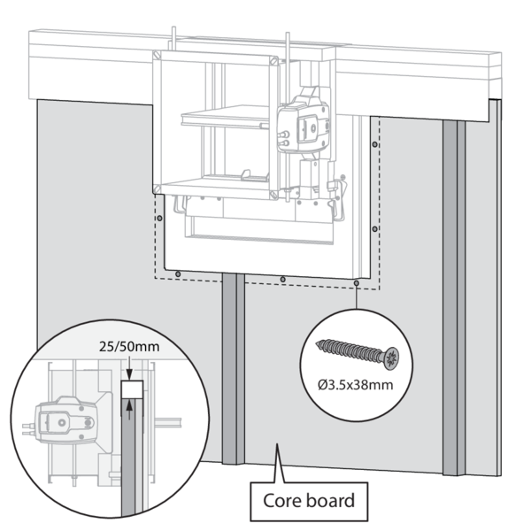
Install the framework and Coreboard. Cut the Coreboard around the damper and fix with plasterboard wood screws Ø3.5 x 38. Release the locks.
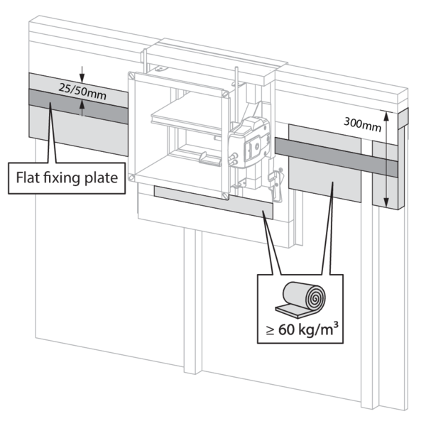
Secure the flat fixing plate at the corresponding distance from the top track (25 or 50 mm). Insulate the deflection head over 300mm. Fill the cavity below the damper with insulation.
Install the plasterboard layers. Respect the deflection head zones towards the slab and below each damper: no plasterboard screws may be fixed above the flat fixing plate nor on/above the insulation zone below the damper.
Finish the top of the partition with mineral wool and an angle profile.
Installation in CLT wall with IFW installation block
The product was tested and approved in:
- Cross-laminated timber ≥ 100 mm | EI 90 (ve i o) S - (300 Pa) | Installation block IFW | Type of installation: built-in 0/90/180/270°. Minimal distances authorised. | 200x100 mm ≤ CU-LT ≤ 800x600 mm
Saw out the installation opening on site if not provided.
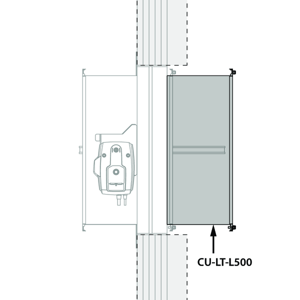
For a wall thickness > 100 mm, it is recommended to provide a longer version of the fire damper (CU-LT-L500). The installation method remains unchanged.
The fire damper may be placed at minimum distance from the ceiling/floor slab.
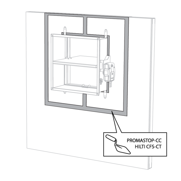
The fire dampers may be placed at minimum distance from each other and from the ceiling/floor slab.
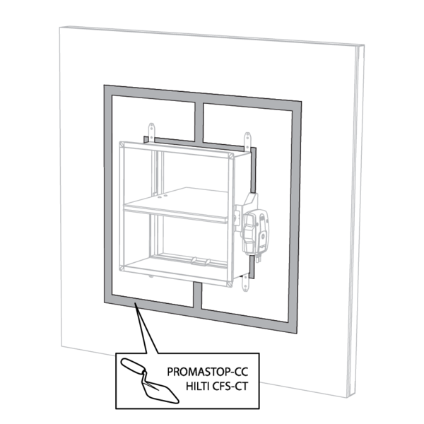
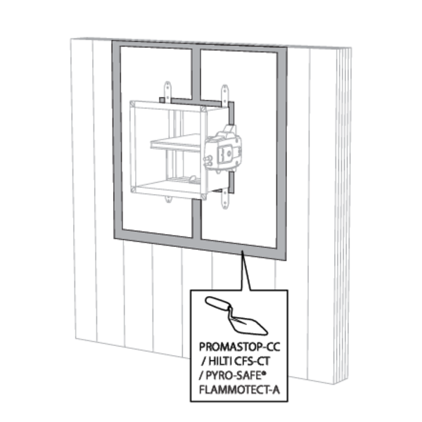
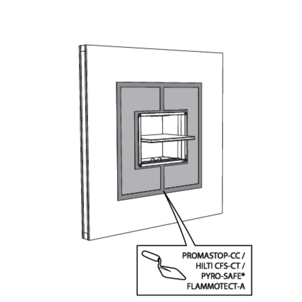
Installation in CLT wall, sealing with batt with coating
The product was tested and approved in:
- Cross-laminated timber ≥ 100 mm | EI 60 (ve i o) S - (300 Pa) | Stone wool + coating ≥ 140 kg/m³ | Type of installation: built-in 0/180°. Minimal distances authorised. | 200x100 mm ≤ CU-LT ≤ 800x600 mm
Saw out the installation opening on site if not provided.
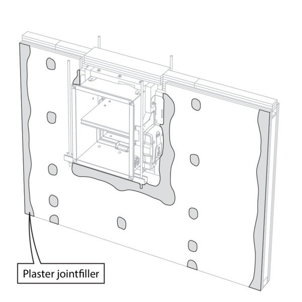
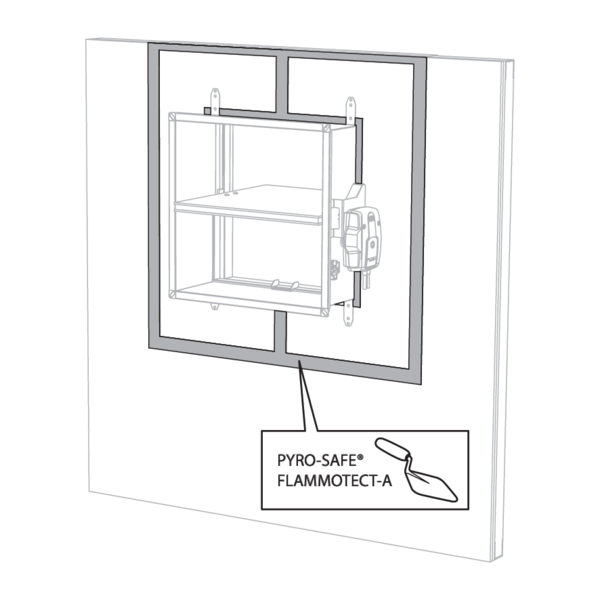
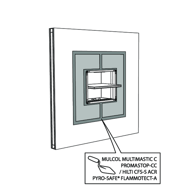
The transition between the cross-laminated timber wall and the sealing can be executed with or without lining (Install 12.5 mm plasterboard in the opening using a filler compound such as PROMASTOP-CC / Hilti CFS-CT / PYRO-SAFE® FLAMMOTECT-A).
The transition between the cross-laminated timber wall and the sealing can be executed with or without lining (Install 12.5 mm plasterboard in the opening using a filler compound such as PROMASTOP-CC / Hilti CFS-CT / PYRO-SAFE® FLAMMOTECT-A).
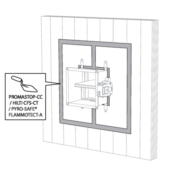
The fire damper may be placed at minimum distance from the ceiling/floor slab.
The transition between the cross-laminated timber wall and the sealing can be executed with or without lining (Install 12.5 mm plasterboard in the opening using a filler compound such as PROMASTOP-CC / Hilti CFS-CT / PYRO-SAFE® FLAMMOTECT-A).
The transition between the cross-laminated timber wall and the sealing can be executed with or without lining (Install 12.5 mm plasterboard in the opening using a filler compound such as PROMASTOP-CC / Hilti CFS-CT / PYRO-SAFE® FLAMMOTECT-A).
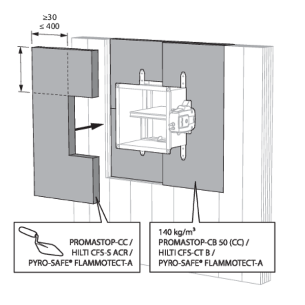
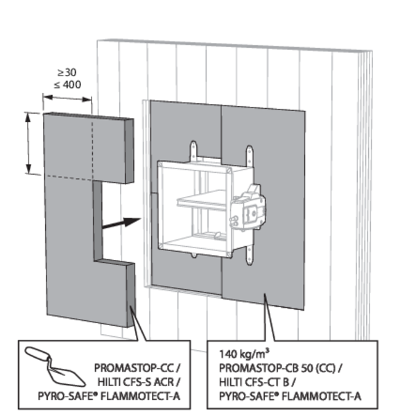
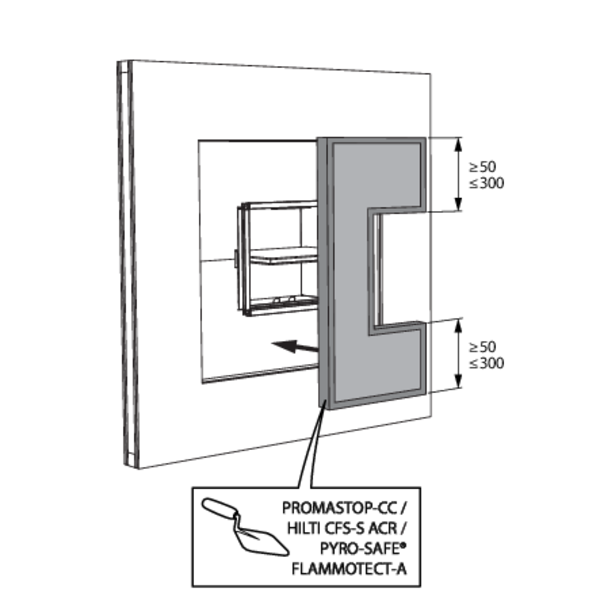
Installation in flexible and rigid wall, sealing with rigid stone wool boards with coating
The product was tested and approved in:
- Aerated concrete ≥ 100 mm | EI 120 (ve i o) S - (300 Pa) | Stone wool + coating ≥ 140 kg/m³ + coated casing | Type of installation: built-in 0/90/180/270°. Minimal distances authorised. | 200x100 mm ≤ CU-LT ≤ 800x600 mm
- Aerated concrete ≥ 100 mm | EI 90 (ve i o) S - (300 Pa) | Stone wool + coating ≥ 140 kg/m³ | Type of installation: built-in 0/90/180/270°. Minimal distances authorised. | 200x100 mm ≤ CU-LT ≤ 800x600 mm
- Metal studs gypsum plasterboard Type A (EN 520) ≥ 100 mm | EI 60 (ve i o) S - (300 Pa) | Stone wool + coating ≥ 140 kg/m³ | Type of installation: built-in 0/90/180/270°. Minimal distances authorised. | 200x100 mm ≤ CU-LT ≤ 800x600 mm
- Metal studs gypsum plasterboard Type F (EN 520) ≥ 100 mm | EI 120 (ve i o) S - (300 Pa) | Stone wool + coating ≥ 140 kg/m³ + coated casing | Type of installation: built-in 0/90/180/270°. Minimal distances authorised. | 200x100 mm ≤ CU-LT ≤ 800x600 mm
- Metal studs gypsum plasterboard Type F (EN 520) ≥ 100 mm | EI 90 (ve i o) S - (300 Pa) | Stone wool + coating ≥ 140 kg/m³ | Type of installation: built-in 0/90/180/270°. Minimal distances authorised. | 200x100 mm ≤ CU-LT ≤ 800x600 mm
For a flexible wall, provide horizontal and vertical studs around the opening. Exception: for fire resistance EI60S and if sealing with PROMASTOP or Hilti type boards, it is not necessary, from a fire technical point of view, to provide studs around the opening.
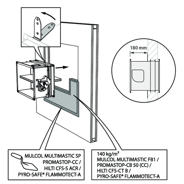
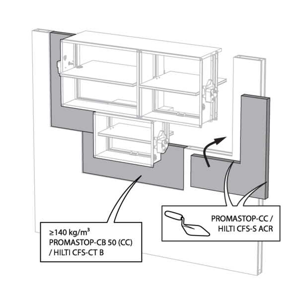
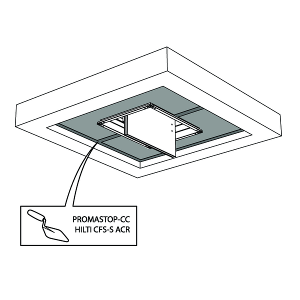
The opening around the damper is sealed with 2 layers of 50 mm-thick mineral wool panels with fire resistant coating on one side (type PROMASTOP-CB 50 / PROMASTOP-CB/CC 50 / HILTI CFS-CT B / Mulcol Multimastic FB1 / PYRO-SAFE® FLAMMOTECT-A).
EI120S only possible with Hilti or Promat material.
EI120S only possible with Hilti or Promat material.
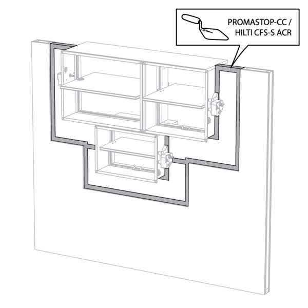
The joints on these 2 layers must be installed staggered and covered all around the edge with coating (type PROMASTOP-CC / HILTI CFS-S-ACR / Mulcol Multimastic SP / PYRO-SAFE® FLAMMOTECT-A).
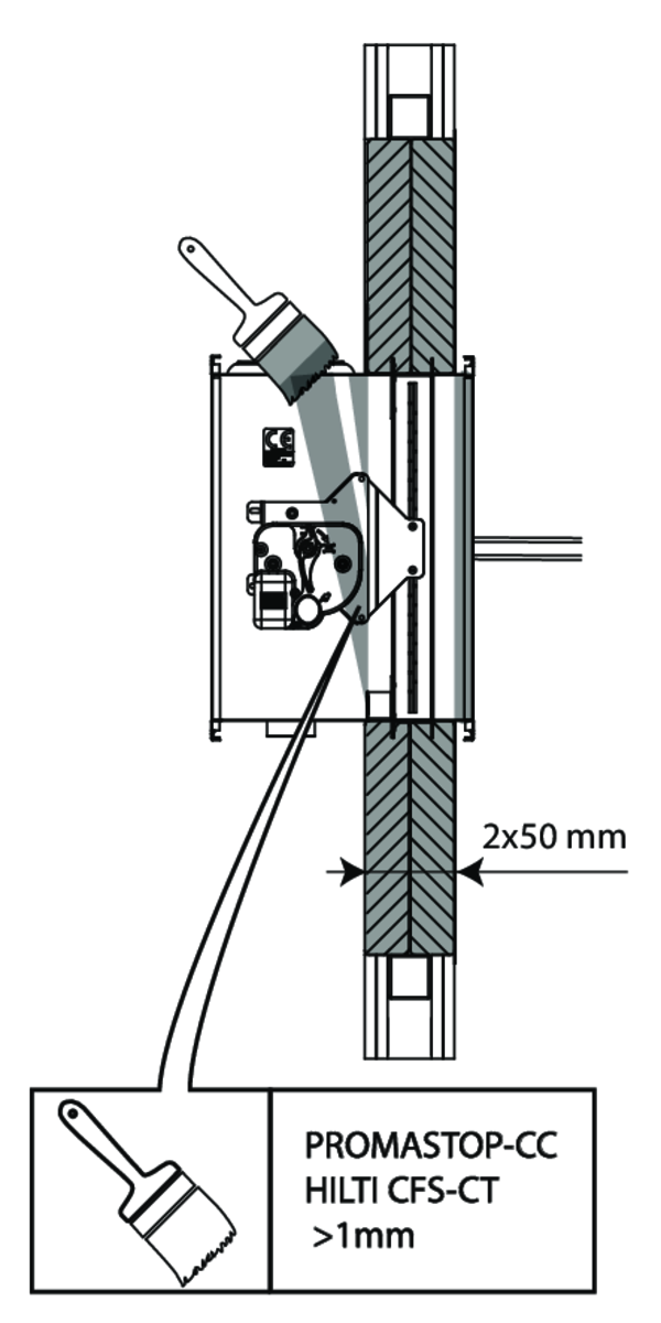
For EI 120 S, the casing of the fire damper must be covered with a layer (> 1 mm) of coating (type PROMASTOP-CC / HILTI CFS-CT) both sides of the wall/partition.
Also apply this coating for EI 60 S if no metal stud profiles were provided around the opening.
Also apply this coating for EI 60 S if no metal stud profiles were provided around the opening.
The damper does not need to be centered in the opening (with max dimensions fire damper + 600 mm). The maximal distance between the damper and the edge of the opening is 400 mm.
The dampers can be installed at a minimum distance from an adjacent floor/ceiling (≥ 25 mm), from an adjacent wall or from another damper (≥ 50 mm).
Build the drywall and mount horizontal and vertical studs around the opening.
When installing a single fire damper at a minimum distance from the ceiling, it is not necessary, from a fire technical point of view, to provide studs around the opening in case of desired fire resistance EI60S.
When installing a single fire damper at a minimum distance from the ceiling, it is not necessary, from a fire technical point of view, to provide studs around the opening in case of desired fire resistance EI60S.
Mount the dampers in the opening.
Apply rigid stone wool panels (≥ 150 kg/m³) to a depth of 400 mm (150 mm on the mechanism side of the wall) to seal the opening at the side with minimal distances.
This sealing is applied over the whole width/height of the damper(s).
When the damper is installed at a distance of 25 mm from a floor/ceiling, the rigid high-density stone wool panels may be replaced with standard ≥ 40 kg/m³ stone wool (e.g. Rockfit 431), compressed by at least 40%.
Apply rigid stone wool panels (≥ 150 kg/m³) to a depth of 400 mm (150 mm on the mechanism side of the wall) to seal the opening at the side with minimal distances.
This sealing is applied over the whole width/height of the damper(s).
When the damper is installed at a distance of 25 mm from a floor/ceiling, the rigid high-density stone wool panels may be replaced with standard ≥ 40 kg/m³ stone wool (e.g. Rockfit 431), compressed by at least 40%.
Seal the rest of the opening with 2 layers of 50 mm-thick coated rigid mineral wool panels (see above).
When installing a single fire damper at a minimum distance from the ceiling: for desired fire resistance EI60S and installation without studs around the opening: apply the coating also to the tunnel of the fire damper.
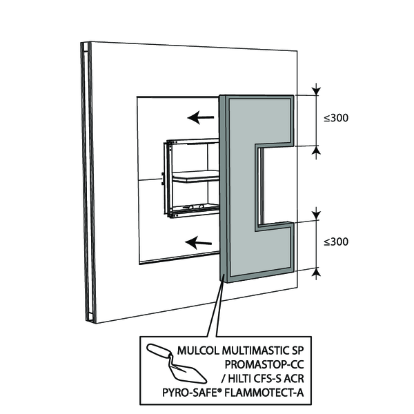
Installation in flexible wall - metal stud with a single layer of plasterboard and sealing with rigid stone wool boards with coating
Fire batt/stone wool boards of type HILTI CFS-CT B may be replaced by a similar type of fire batt with at least the same fire reaction class, density and thickness (tested according to EN 1366-3).
The partition is built with a single layer of plasterboard either side. Both I- and C-studs are allowed.
The opening around the damper is sealed with 2 layers of 50 mm-thick mineral wool panels with fire resistant coating on one side (type HILTI CFS-CT B).
The joints on these 2 layers must be installed staggered and covered all around the edge with coating (type HILTI CFS-S-ACR).
The damper does not need to be centered in the opening (with max dimensions fire damper + 600 mm). The maximal distance between the damper and the edge of the opening is 300 mm.
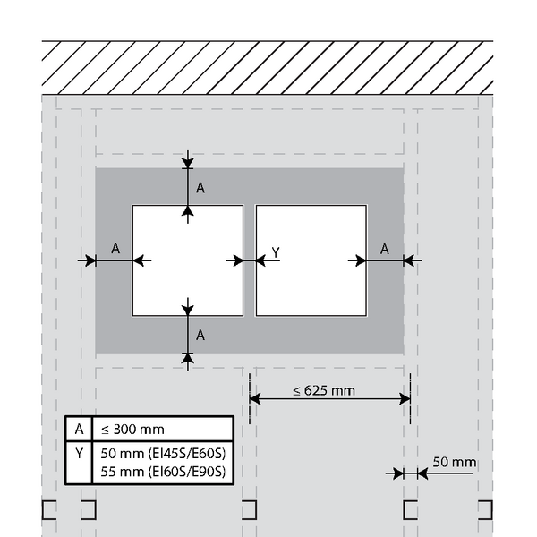
Max. 2 dampers can be installed at a minimum distance from each other: 50 mm if EI45S/E60S and 55 mm if EI60S/E90S.
Installation in flexible wall (timber stud), sealing with rigid stone wool boards with coating
The product was tested and approved in:
- Timber studs gypsum plasterboard Type A (EN 520) ≥ 100 mm | EI 60 (ve i o) S - (300 Pa) | Stone wool + coating ≥ 140 kg/m³ | Type of installation: built-in 0/180° | 200x100 mm ≤ CU-LT ≤ 800x600 mm
- Timber studs gypsum plasterboard Type F (EN 520) ≥ 100 mm | EI 90 (ve i o) S - (300 Pa) | Stone wool + coating ≥ 140 kg/m³ | Type of installation: built-in 0/180° | 200x100 mm ≤ CU-LT ≤ 800x600 mm
The opening around the damper is sealed with 2 rigid stone wool boards of 50 mm. These boards should be placed in a slanted position and the joints should be covered all around with filling paste.
The damper does not need to be centered in the opening (with max dimensions Wn x Hn fire damper + 600 mm). The maximal distance between the damper and the edge of the opening is 300 mm.
Installation in rigid floor, sealing with rigid stone wool boards with coating
The product was tested and approved in:
- Aerated concrete ≥ 150 mm | EI 120 (ho i o) S - (300 Pa) | Stone wool + coating ≥ 140 kg/m³ + coated casing | Type of installation: built-in 0/90/180/270°. Minimal distances authorised. | 200x100 mm ≤ CU-LT ≤ 800x600 mm
- Aerated concrete ≥ 150 mm | EI 90 (ho i o) S - (300 Pa) | Stone wool + coating ≥ 140 kg/m³ | Type of installation: built-in 0/90/180/270°. Minimal distances authorised. | 200x100 mm ≤ CU-LT ≤ 800x600 mm
The opening around the damper is sealed with 2 layers of 50 mm-thick mineral wool panels with fire resistant coating on one side (type PROMASTOP-CB 50 / PROMASTOP-CB/CC 50 / HILTI CFS-CT B).
The joints on these 2 layers must be installed staggered and covered all around the edge with coating (type PROMASTOP-CC / HILTI CFS-S-ACR).
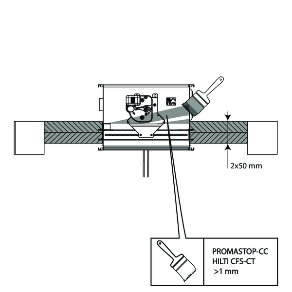
For EI 120 S, the casing of the fire damper must be covered with a layer (> 1 mm) of coating (type PROMASTOP-CC / HILTI CFS-CT) both sides of the floor.
(only for 120 minutes)
(only for 120 minutes)
The damper does not need to be centered in the opening (with max dimensions fire damper + 600 mm). The maximal distance between the damper and the edge of the opening is 400 mm.
The dampers can be installed at a minimum distance from an adjacent wall or from another damper (≥ 50 mm).
For details, please refer to 'Installation in flexible and rigid wall, sealing with rigid stone wool boards with coating'
For details, please refer to 'Installation in flexible and rigid wall, sealing with rigid stone wool boards with coating'
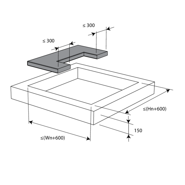
Installation remote from the wall, sealing and insulation with rigid stone wool boards with coating
The product was tested and approved in:
- Aerated concrete ≥ 100 mm | EI 60 (ve i o) S - (300 Pa) | Galvanised duct + stone wool + coating ≥ 140 kg/m³ 1x60 mm + installation block IFW | Type of installation: remote from the wall, 0/180°. Minimal distances authorised. | 200x100 mm ≤ CU-LT ≤ 800x600 mm
- Aerated concrete ≥ 100 mm | EI 90 (ve i o) S - (300 Pa) | Galvanised duct + stone wool + coating ≥ 140 kg/m³ 1x80 mm + IFW installation block | Type of installation: remote from the wall, 0/180°. Minimal distances authorised. | 200x100 mm ≤ CU-LT ≤ 800x600 mm
- Aerated concrete ≥ 100 mm | EI 90 (ve i o) S - (300 Pa) | Galvanised duct + stone wool + coating ≥ 140 kg/m³ 2x50 mm + installation block IFW | Type of installation: remote from the wall, 0/180°. Minimal distances authorised. | 200x100 mm ≤ CU-LT ≤ 800x600 mm
- Metal studs gypsum plasterboard Type A (EN 520) ≥ 100 mm | EI 60 (ve i o) S - (300 Pa) | Galvanised duct + stone wool + coating ≥ 140 kg/m³ 1x60 mm + installation block IFW | Type of installation: remote from the wall, 0/180°. Minimal distances authorised. | 200x100 mm ≤ CU-LT ≤ 800x600 mm
- Metal studs gypsum plasterboard Type A (EN 520) ≥ 100 mm | EI 60 (ve i o) S - (300 Pa) | Galvanised duct + stone wool + coating ≥ 140 kg/m³ 2x50 mm + installation block IFW | Type of installation: remote from the wall, 0/180°. Minimal distances authorised. | 200x100 mm ≤ CU-LT ≤ 800x600 mm
- Metal studs gypsum plasterboard Type F (EN 520) ≥ 100 mm | EI 90 (ve i o) S - (300 Pa) | Galvanised duct + stone wool + coating ≥ 140 kg/m³ 2x50 mm + installation block IFW | Type of installation: remote from the wall, 0/180°. Minimal distances authorised. | 200x100 mm ≤ CU-LT ≤ 800x600 mm
For classification to EI60S: the fire batt type PROMASTOP-CB60 or CB-CC50 may be replaced by a similar type of fire batt with at least the same fire reaction class, density and thickness (tested according to EN 1366-3).
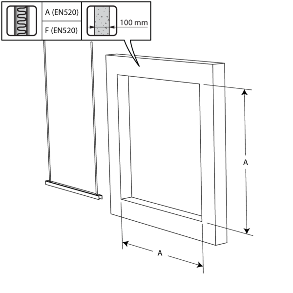
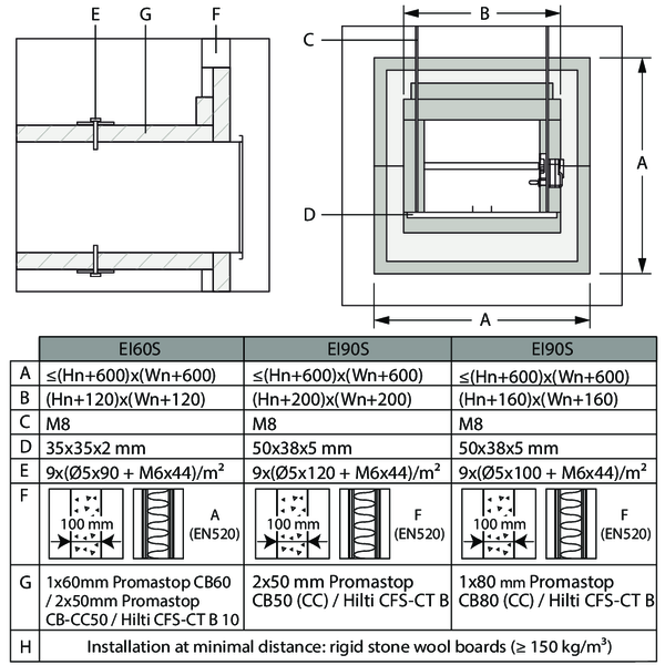
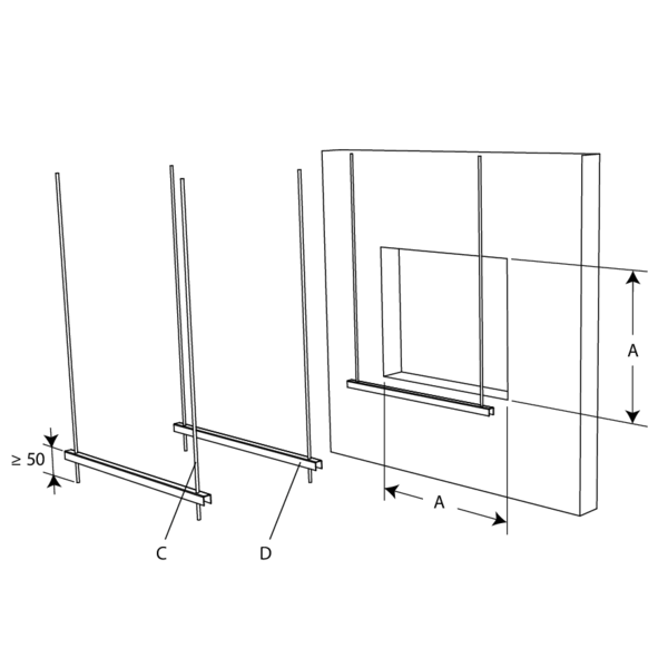
An opening with maximal dimensions “A” is made in the wall. For a light partition wall, follow the wall assembly under “Installation in flexible or rigid wall - Sealing with fire resistant rigid panels of stone wool“.
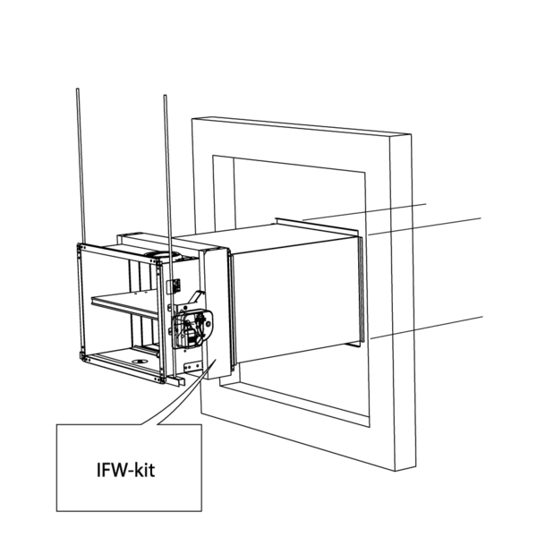
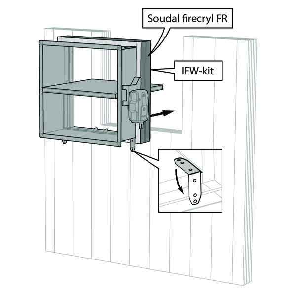
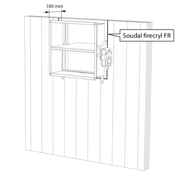
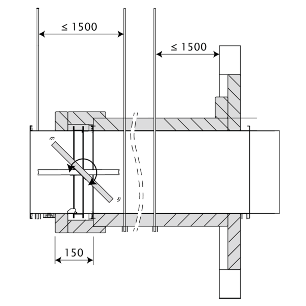
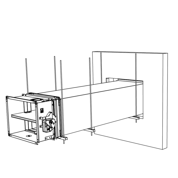
The fire damper is equipped with the IFW kit and mounted remote from the wall at the end of a metal duct. The duct is supported every 1500 mm as well as underneath the damper.
The suspensions consist of threaded rods “C” and U-shaped steel profiles “D”. A free space of maximum 25 mm is left between the threaded rods and the vertical walls of the stone wool casing “B”.
The suspensions consist of threaded rods “C” and U-shaped steel profiles “D”. A free space of maximum 25 mm is left between the threaded rods and the vertical walls of the stone wool casing “B”.
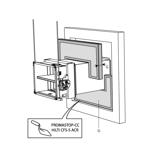
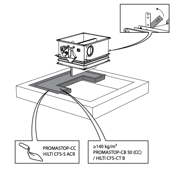
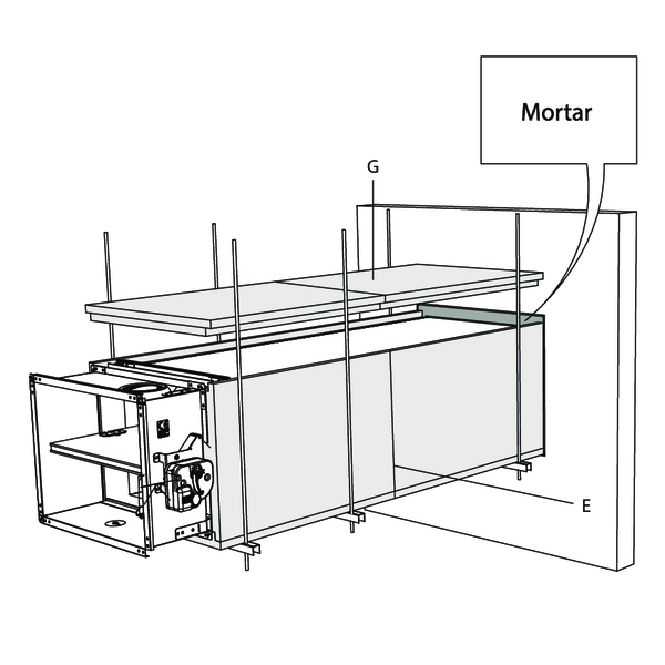
The opening around the duct is sealed with stone wool plates type PROMASTOP-CB(/CC) / Hilti CFS-CT B (“G”). The edges are sealed and maintained in place with PROMASTOP-CC / HILTI CFS-S ACR coating.
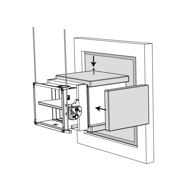
The duct is covered over its entire length with stone wool plates “G”. To adhere to the duct, the plates are completely coated on one side with fire resitant coating and affixed to the duct with steel screws and washers “E”.
The damper casing is covered with stone wool plates “G” for 150 mm. A free space is left around the mechanism to allow access.
The joints between the plates, between the wall and the plates as well as the screws and washers are filled with coating PROMASTOP-CC / HILTI CFS-S ACR.
The damper casing is covered with stone wool plates “G” for 150 mm. A free space is left around the mechanism to allow access.
The joints between the plates, between the wall and the plates as well as the screws and washers are filled with coating PROMASTOP-CC / HILTI CFS-S ACR.
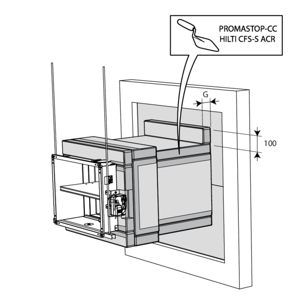
An additional mineral wool panel with width “B” and height 100 mm, coated with PROMASTOP-CC / HILTI CFS-S ACR, is applied where the stone wool casing meets the sealing of the wall opening.


The dampers can be installed at a minimum distance from an adjacent floor/ceiling, from an adjacent wall or from another damper.


Apply rigid stone wool panels (≥ 150 kg/m³) to a depth of 400 mm (150 mm on the mechanism side of the wall) to seal the opening at the side with minimal distances.
When the distance between the damper and the wall is greater than 75 mm, the sealing of the opening between the damper and the wall is carried out according to the pre-existing classification.
When the distance between the damper and the wall is greater than 75 mm, the sealing of the opening between the damper and the wall is carried out according to the pre-existing classification.


Installation remote from the wall + GEOFLAM
The product was tested and approved in:
- Aerated concrete ≥ 100 mm | EI 120 (ve i o) S - (500 Pa) | Galvanised duct + GEOFLAM® N 35 mm + mortar | Type of installation: remote from the wall, 0/180°. Minimal distances authorised. | 200x100 mm ≤ CU-LT ≤ 800x600 mm
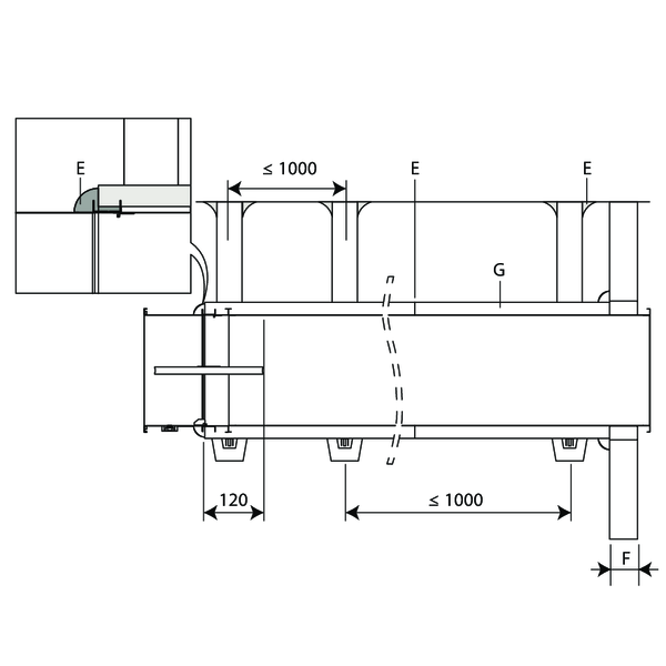
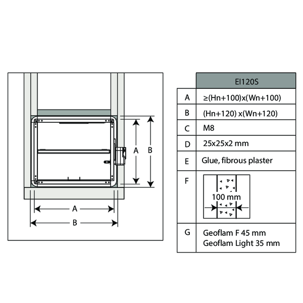
An opening with maximal dimensions “A” is made in the wall.
The fire damper is mounted remote from the wall at the end of a metal duct. The duct is supported every 1000 mm.
The suspensions consist of threaded rods “C” and U-shaped steel profiles “D”. A free space of maximum 25 mm is left between the threaded rods and the vertical walls of the casing “B”.
The suspensions consist of threaded rods “C” and U-shaped steel profiles “D”. A free space of maximum 25 mm is left between the threaded rods and the vertical walls of the casing “B”.
The opening around the duct is sealed with standard mortar. The duct is covered with 35 mm thick GEOFLAM N plates "G”.
The plates adhere to each other with glue and fibrous plaster “E”. The damper casing is also covered on a length of 120 mm.
The plates adhere to each other with glue and fibrous plaster “E”. The damper casing is also covered on a length of 120 mm.
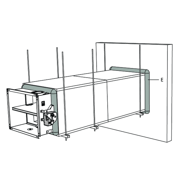
The GEOFLAM N plates stop at a distance of 15 mm from the wall. The free space is filled with fibrous plaster.
The same filling is applied to seal off the connection between the GEOFLAM F plates and the damper casing.
The same filling is applied to seal off the connection between the GEOFLAM F plates and the damper casing.
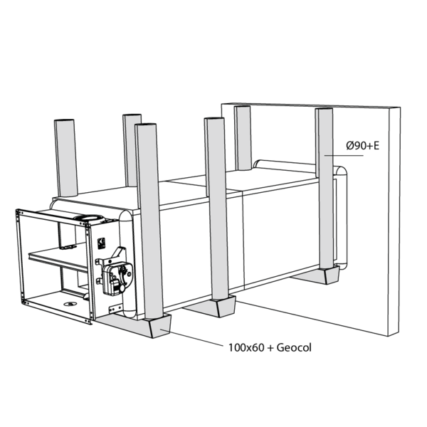
The threaded rods are covered with U-shaped plates of GEOFLAM (Ø 90 mm) and affixed with glue and fibrous plaster.
The profiles are covered with U-shaped shells GEOFLAM 100 x 60 mm, which are affixed to the underside of the shaft with GEOCOL (GEOSTAFF) cement plaster.
The profiles are covered with U-shaped shells GEOFLAM 100 x 60 mm, which are affixed to the underside of the shaft with GEOCOL (GEOSTAFF) cement plaster.

The dampers can be installed at a minimum distance from an adjacent floor/ceiling (≥ 25 mm), from an adjacent wall or from another damper (≥ 50 mm).


Apply rigid stone wool panels (≥ 150 kg/m³) to a depth of 400 mm (150 mm on the mechanism side of the wall) to seal the opening at the side with minimal distances.


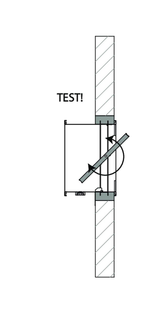
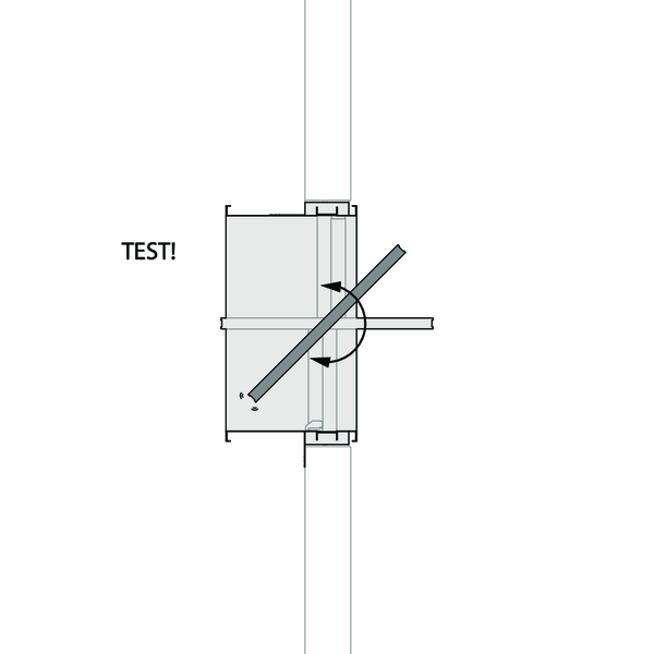
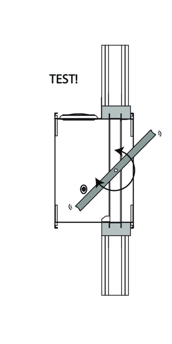
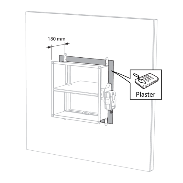
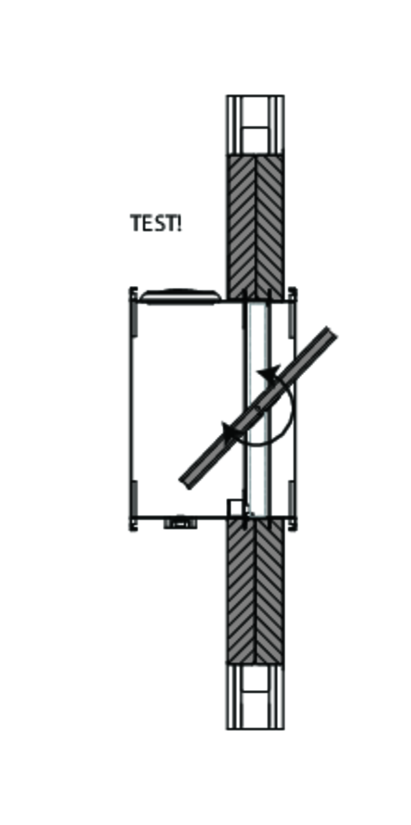
Position of the thermo-electric fuse (spring-return actuator BFLT)
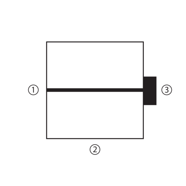
Position of the thermo-electric fuse on the damper casing: 1. on opposite side of mechanism if H < 250 mm and W < 250 mm; 2. at the bottom if H < 250 mm and W ≥ 250 mm; 3. on mechanism side if H ≥ 250 mm.
General remarks
- The installation must comply with the installation manual and the classification report.
- Axis orientation: see the declaration of performance.
- Avoid obstruction of adjoining ducts.
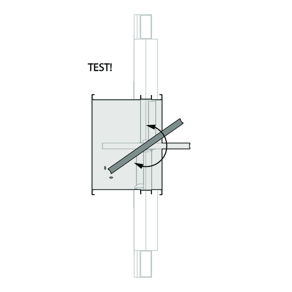
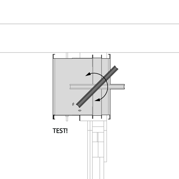
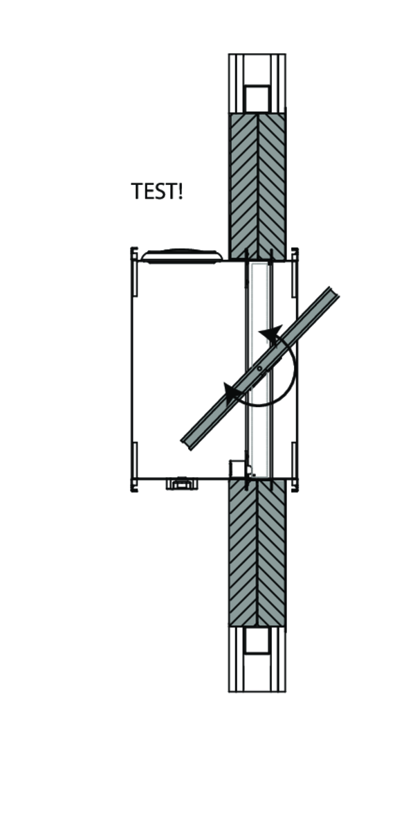
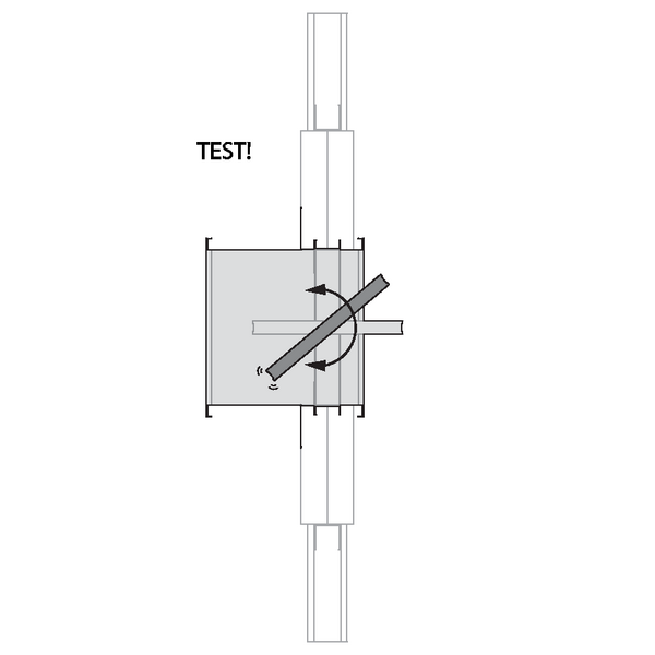
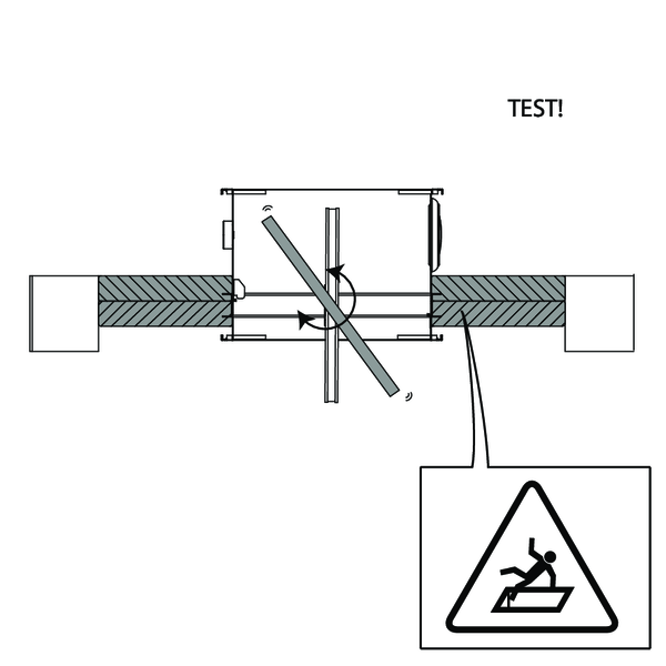
- Product installation: always with closed damper blade.
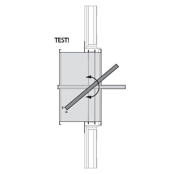
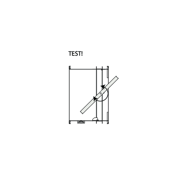
- Verify if the blade can move freely.
- Please observe safety distances with respect to other construction elements. The operating mechanism must also remain accessible: allow for a clearance of 200 mm around the housing.
- The air tightness class will be maintained if the damper is installed according to the installation manual.
- Rf-t fire dampers are always tested in standardised constructions according to EN 1366-2. The achieved results are valid for similar supporting constructions with a fire resistance, thickness and density equal or superior to the supporting construction used during the test.
- If the wall thickness exceeds the minimum thickness specified in our installation instructions, the following conditions apply to the sealing depth: - For flexible walls and sandwich panel system walls, the seal must always be applied over the full depth of the wall. - With rigid walls, rigid floors and plaster block walls, the minimum sealing depth as indicated in our installation instructions (often equal to the minimum wall thickness) is sufficient. Apply the seal at the height of the damper blade (from the wall limit indication).
- When installing a fire damper in a flexible metal stud wall, some installation methods do not require reinforcing profiles around the wall opening from a fire protection point of view (see below). Always follow the general instructions of the manufacturer of these wall systems when building this type of wall.
- The damper must remain accessible for inspection and maintenance.
- Schedule at least 2 visual checks each year.