MARKAGE FD - Installation
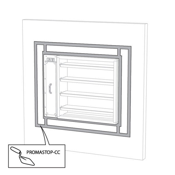
Installation in rigid wall, sealing with mortar
The product was tested and approved in:
- Aerated concrete ≥ 100 mm | EI 90 (ve i o) S (300Pa) | Mortar | Type of installation: built-in 0/90/180/270° | 200x200 mm ≤ MARKAGE FD ≤ 1000x2400 mm
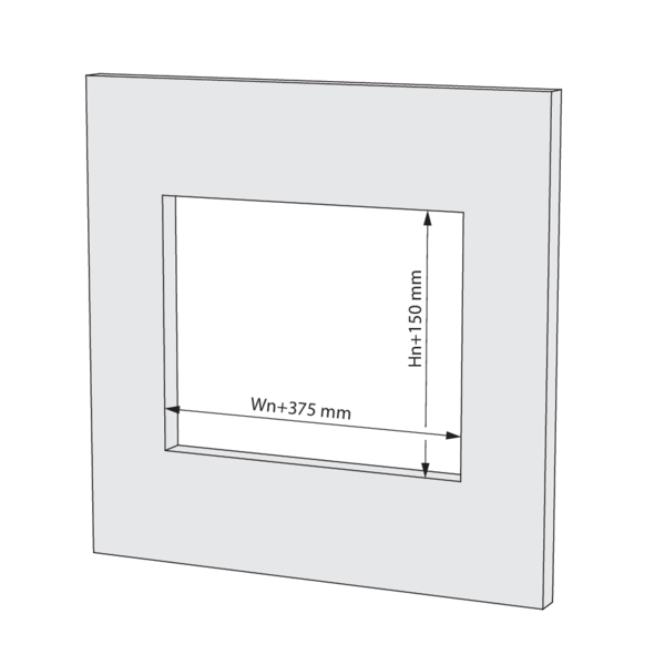
Make an opening with dimensions (Wn+375) x (Hn+150) mm.
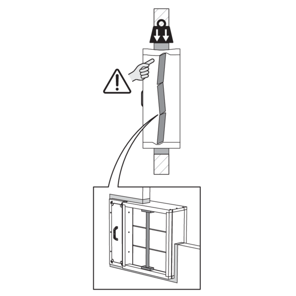
Mount the damper in the opening.
Support the tunnel and block the damper blades in the closed position to prevent deformation of the tunnel while the sealing is curing.
Support the tunnel and block the damper blades in the closed position to prevent deformation of the tunnel while the sealing is curing.
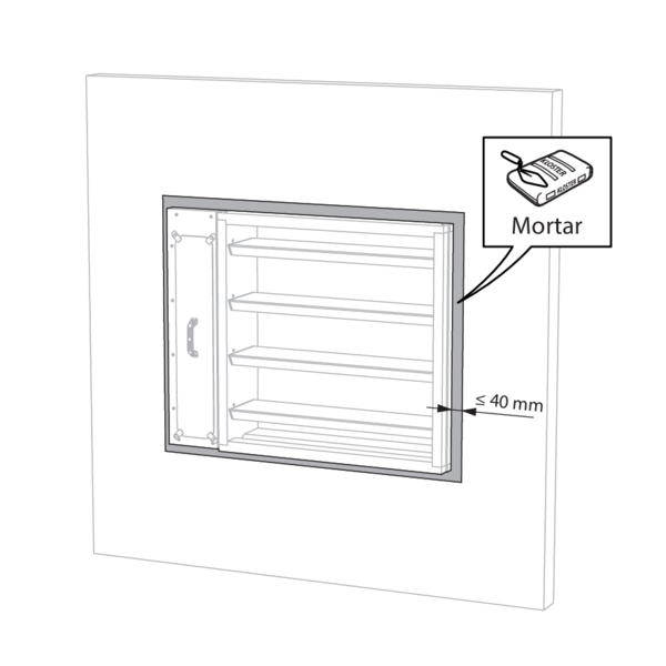
Seal the rest of the opening with standard mortar.
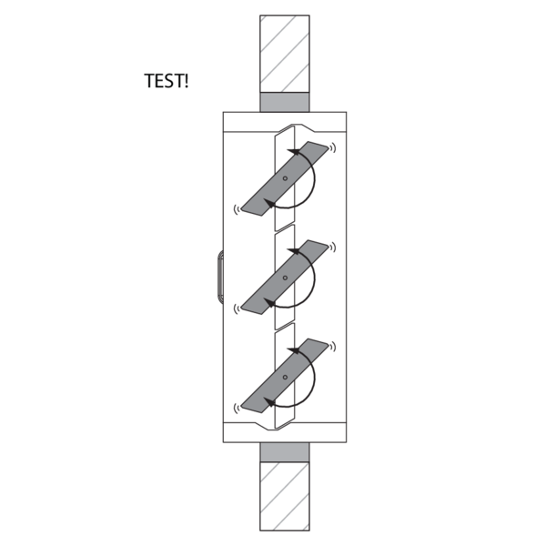
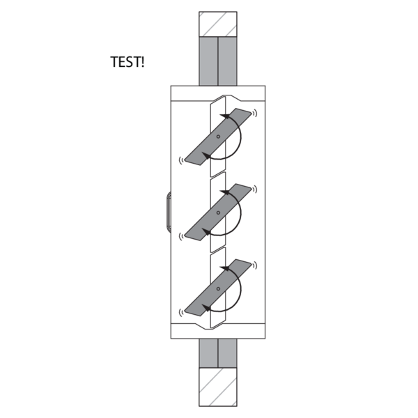
Check the functioning of the damper blades after the curing time of the sealing and after removing the struts.
Test the mechanism of the damper.
Test the mechanism of the damper.
Installation in rigid wall, sealing with rigid stone wool boards with coating
The product was tested and approved in:
- Aerated concrete ≥ 100 mm | EI 90 (ve i o) S (300Pa) | Stone wool + coating ≥ 140 kg/m³ | Type of installation: built-in 0/90/180/270° | 200x200 mm ≤ MARKAGE FD ≤ 1000x2400 mm
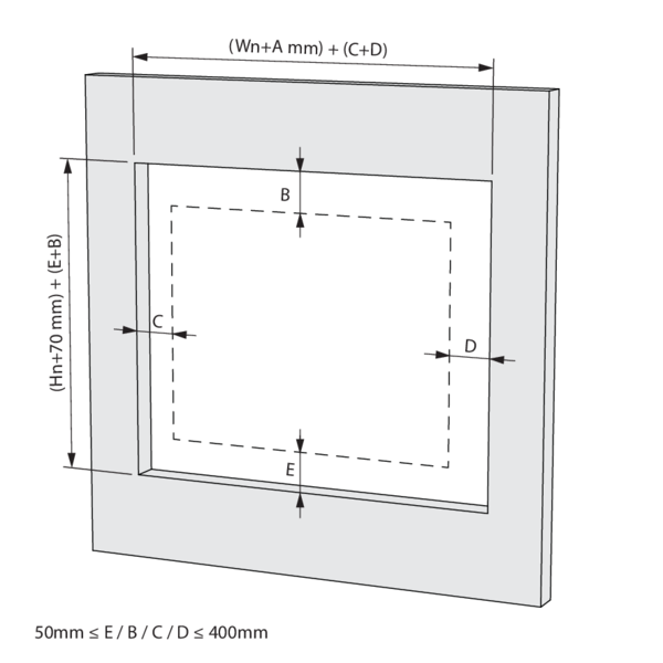
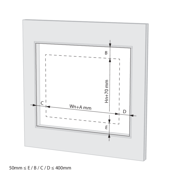
Make an opening with dimensions (Wn+295+C+D) x (Hn+70+B+E) mm.
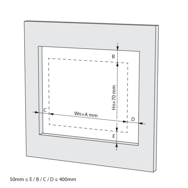
Mount the damper in the opening. Sealing B, C, D & E between 50 and 400 mm each.
The damper does not need to be centered in the opening. The maximum distance between the damper and the edge of the opening is 400 mm.
The damper does not need to be centered in the opening. The maximum distance between the damper and the edge of the opening is 400 mm.
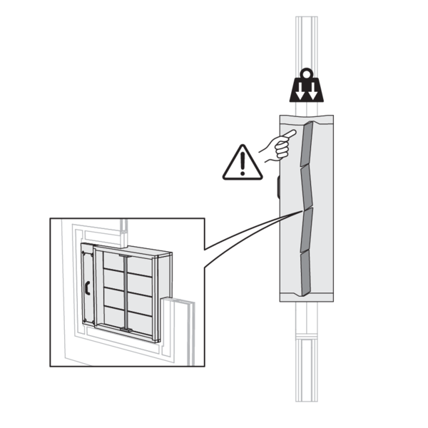
Support the tunnel and block the damper blades in the closed position to prevent deformation of the tunnel while the sealing is curing.
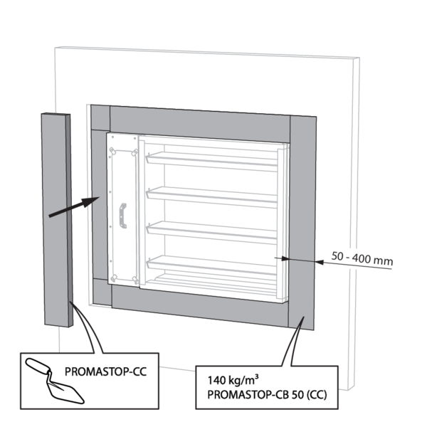
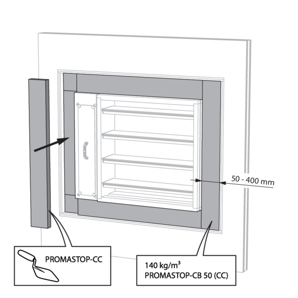
Seal the rest of the opening with 2 layers of 50 mm thick coated rigid mineral wool panels (type PROMASTOP CB-CC). The panels must be installed staggered. When installing, always apply coating (type PROMASTOP-CC) to the end of each panel.
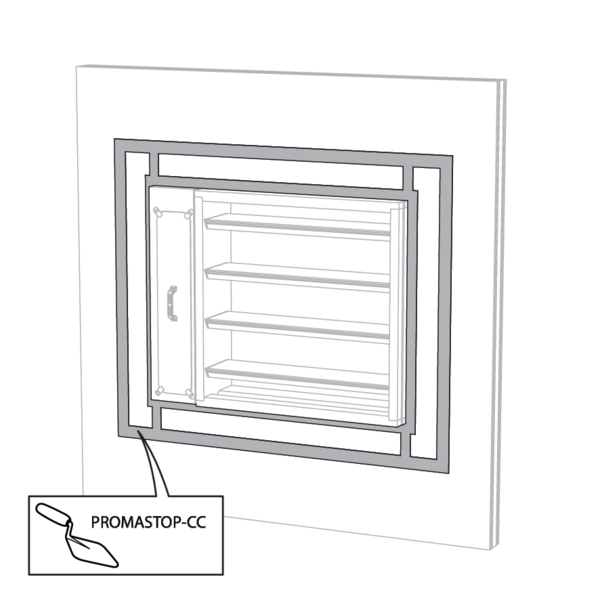
The panels must be installed staggered and the joints must be covered all around with coating (type PROMASTOP-CC) to create a uniform layer thickness for the entire sealing.
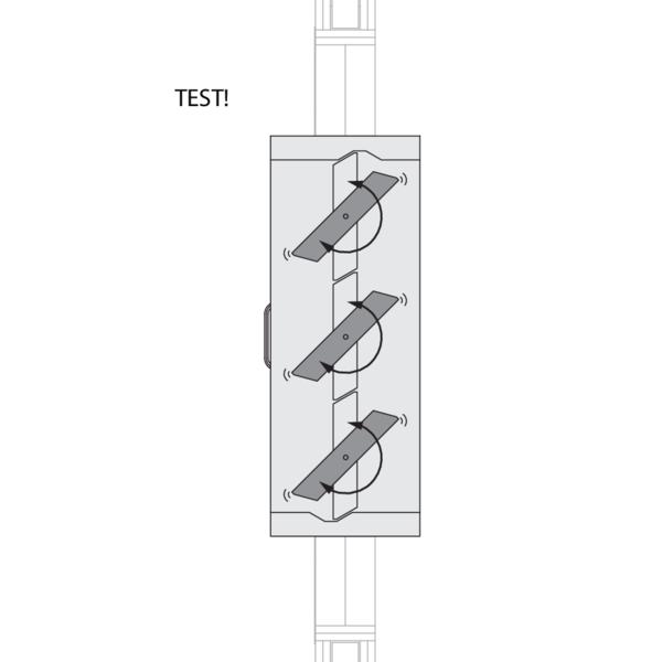
Check the functioning of the damper blades after the curing time of the sealing and after removing the struts.
Test the mechanism of the damper.
Test the mechanism of the damper.
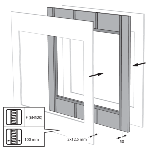
Installation in flexible wall, sealing with rigid stone wool boards with coating
The product was tested and approved in:
- Metal studs gypsum plasterboard Type F (EN 520) ≥ 100 mm | EI 90 (ve i o) S (300Pa) | Stone wool + coating ≥ 140 kg/m³ | Type of installation: built-in 0/90/180/270° | 200x200 mm ≤ MARKAGE FD ≤ 1000x2400 mm
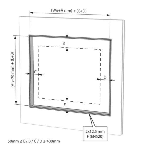
Make an opening with dimensions (Wn+295+C+D) x (Hn+70+B+E) mm.
Mount the damper in the opening. Sealing B, C, D & E between 50 and 400 mm each.
The damper does not need to be centered in the opening. The maximum distance between the damper and the edge of the opening is 400 mm.
The damper does not need to be centered in the opening. The maximum distance between the damper and the edge of the opening is 400 mm.
Support the tunnel and block the damper blades in the closed position to prevent deformation of the tunnel while the sealing is curing.
Seal the rest of the opening with 2 layers of 50 mm thick coated rigid mineral wool panels (type PROMASTOP CB-CC). The panels must be installed staggered. When installing, always apply coating (type PROMASTOP-CC) to the end of each panel.
The panels must be installed staggered and the joints must be covered all around with coating (type PROMASTOP-CC) to create a uniform layer thickness for the entire sealing.
Check the functioning of the damper blades after the curing time of the sealing and after removing the struts.
Test the mechanism of the damper.
Test the mechanism of the damper.
Installation with vertical suspension (VS MAS)
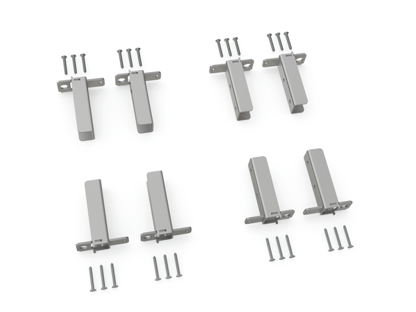
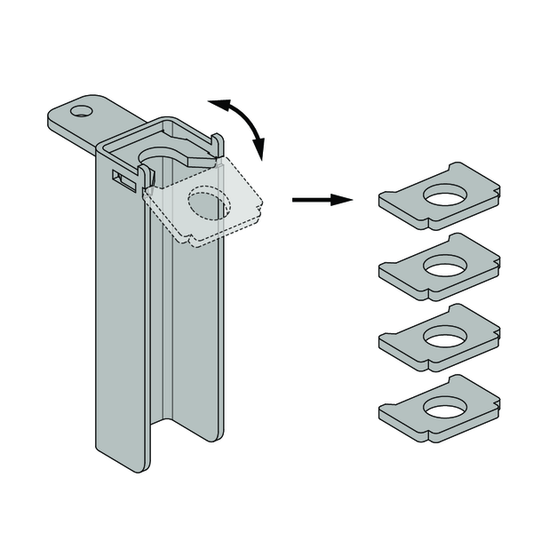
Break off the tabs of the angle brackets and save them for further installation.
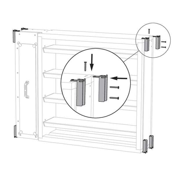
Fit the angle brackets on the corners of the damper.
The orientation depends on the desired orientation of the damper (vertical or horizontal damper blades).
Align the U-profiles of the angle brackets with one another and note the vertical direction. The short side of each angle bracket, with one screw, should be on the top or bottom of the damper.
The orientation depends on the desired orientation of the damper (vertical or horizontal damper blades).
Align the U-profiles of the angle brackets with one another and note the vertical direction. The short side of each angle bracket, with one screw, should be on the top or bottom of the damper.
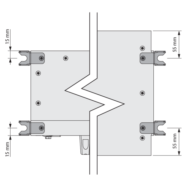
Attach the angle brackets with the supplied screws Ø 5x35 mm. The screws near the connection compartment are 15 mm from the edge, while screws in the tunnel wall are 55 mm from the edge.
Position the damper in the opening of the wall according to the guidelines for each wall type.
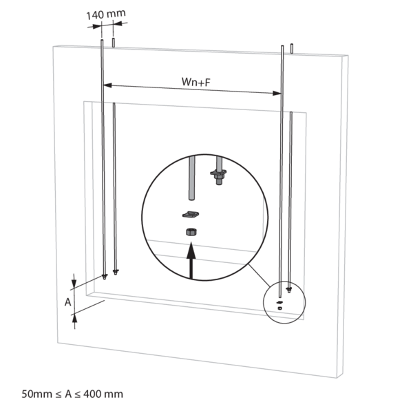
Fit the threaded rods (≥ M10) for damper suspension on the front and back of the wall, with F = 320 mm. Put a tab and a nut on each threaded rod. Align all tabs at the same height.
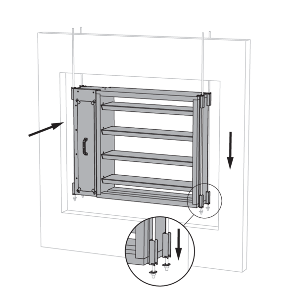
Place the damper on the tabs. The threaded rods must be inside the U profiles of the angle brackets. Make sure to secure the tabs to the bottom angle brackets.
When passing through the compartment wall, the suspension must not be insulated. When installed in ducts, the suspension must be insulated in the same way as the suspension of the duct.
When passing through the compartment wall, the suspension must not be insulated. When installed in ducts, the suspension must be insulated in the same way as the suspension of the duct.
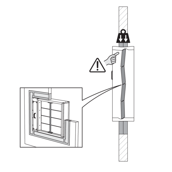
Support the tunnel and block the damper blades in the closed position to prevent deformation of the tunnel while the sealing is curing.
Complete the sealing of the damper according to the guidelines per wall type.
Complete the sealing of the damper according to the guidelines per wall type.
General remarks
- The installation must comply with the installation manual and the classification report.
- Axis orientation: see the declaration of performance.
- Avoid obstruction of adjoining ducts.
- Product installation: always with closed damper blade.
- Verify if the blade can move freely.
- Please observe safety distances with respect to other construction elements. The operating mechanism must also remain accessible: allow for a clearance of 200 mm around the housing.
- The air tightness class will be maintained if the damper is installed according to the installation manual.
- Rf-t fire dampers are always tested in standardised constructions according to EN 1366-2. The achieved results are valid for similar supporting constructions with a fire resistance, thickness and density equal or superior to the supporting construction used during the test.
- If the wall thickness exceeds the minimum thickness specified in our installation instructions, the following conditions apply to the sealing depth: - For flexible walls and sandwich panel system walls, the seal must always be applied over the full depth of the wall. - With rigid walls, rigid floors and plaster block walls, the minimum sealing depth as indicated in our installation instructions (often equal to the minimum wall thickness) is sufficient. Apply the seal at the height of the damper blade (from the wall limit indication).
- When installing a fire damper in a flexible metal stud wall, some installation methods do not require reinforcing profiles around the wall opening from a fire protection point of view (see below). Always follow the general instructions of the manufacturer of these wall systems when building this type of wall.
- The damper must remain accessible for inspection and maintenance.
- Schedule at least 2 visual checks each year.