MARKAGE MB-1S - Installation
Installation in rigid wall
The product was tested and approved in:
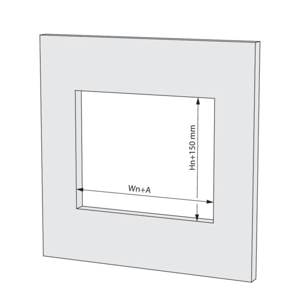
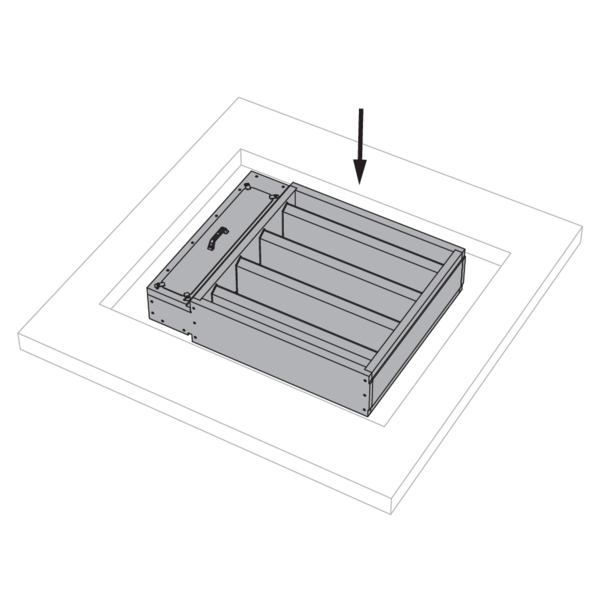
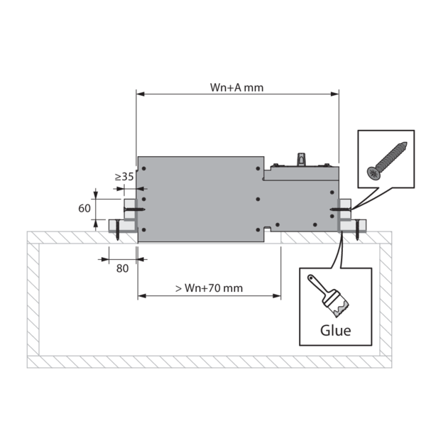
Make an opening with dimensions (Wn+A) x (Hn+150) mm. A = 375 mm for a standard damper. Caution: for a damper with height ≤ 400 mm and option BP FM or ZENiX 1SD, A = 545 mm.
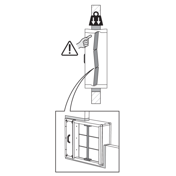
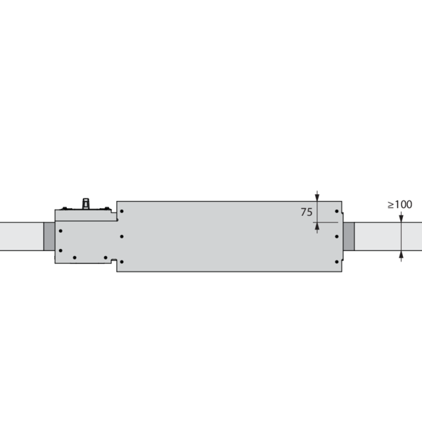
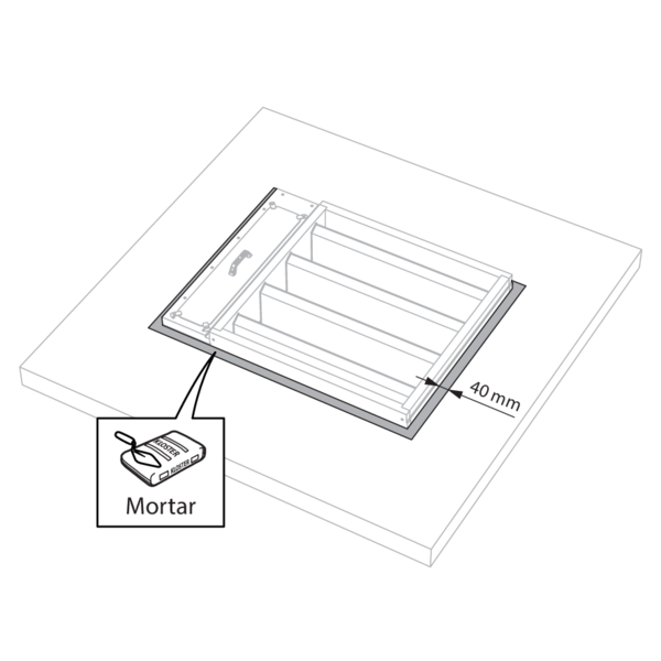
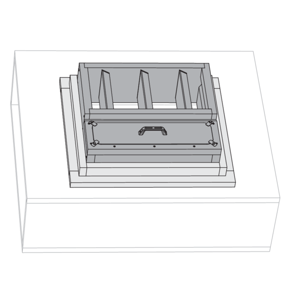
Mount the damper in the opening.
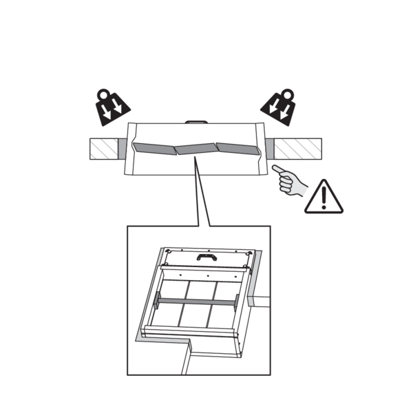
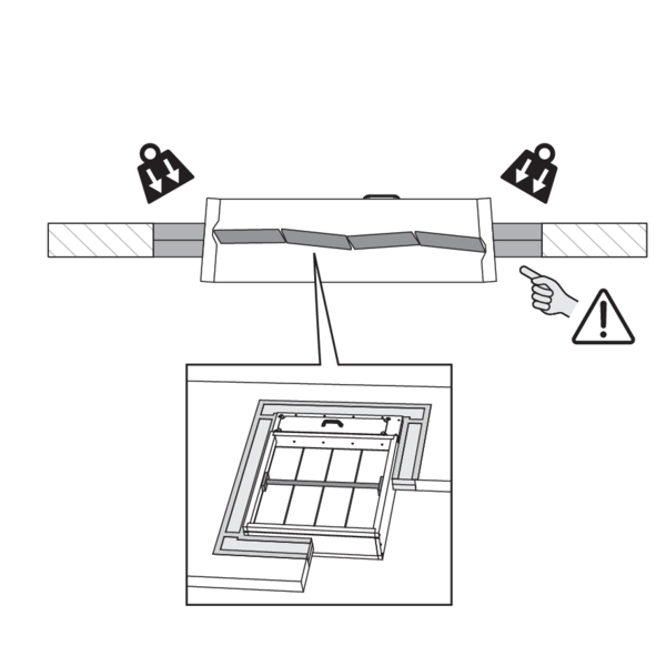
Support the tunnel and block the damper blades in the closed position to prevent deformation of the tunnel while the sealing is curing.
Support the tunnel and block the damper blades in the closed position to prevent deformation of the tunnel while the sealing is curing.
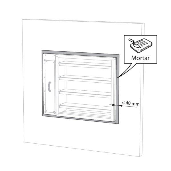
Seal the rest of the opening with standard mortar.
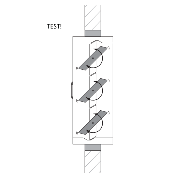
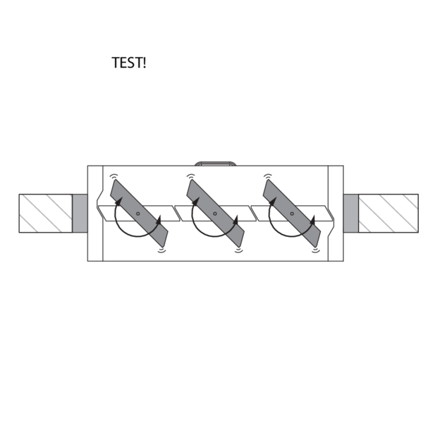
Check the functioning of the damper blades after the curing time of the sealing and after removing the struts.
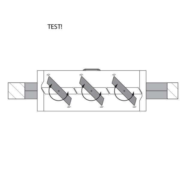
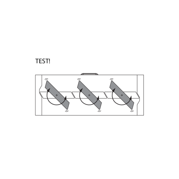
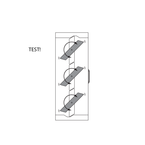
Test the mechanism of the damper.
Test the mechanism of the damper.
Installation in rigid wall, sealing with rigid stone wool boards with coating
The product was tested and approved in:
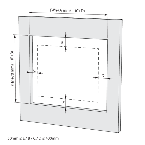
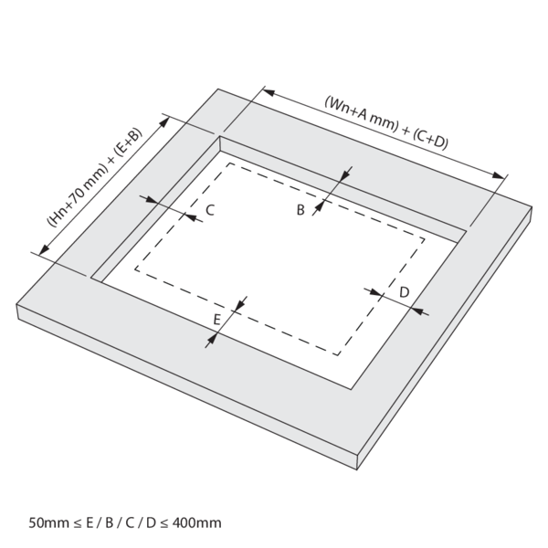
Make an opening with dimensions (Wn+A+C+D) x (Hn+70+B+E) mm. A = 295 mm for a standard damper. Caution: for a damper with height ≤ 400 mm and option BP FM or ZENiX 1SD, A = 465 mm.
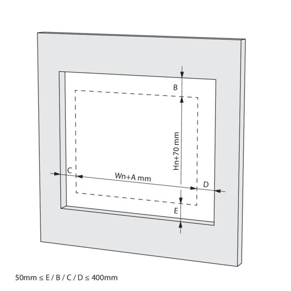
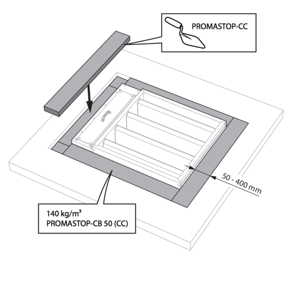
Mount the damper in the opening. Sealing B, C, D & E between 50 and 400 mm each.
The damper does not need to be centered in the opening. The maximum distance between the damper and the edge of the opening is 400 mm.
The damper does not need to be centered in the opening. The maximum distance between the damper and the edge of the opening is 400 mm.
Support the tunnel and block the damper blades in the closed position to prevent deformation of the tunnel while the sealing is curing.
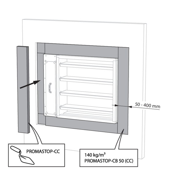
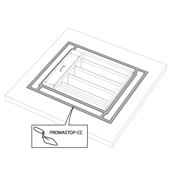
Seal the rest of the opening with 2 layers of 50 mm thick coated rigid mineral wool panels (type PROMASTOP CB-CC). The panels must be installed staggered. When installing, always apply coating (type PROMASTOP-CC) to the end of each panel.
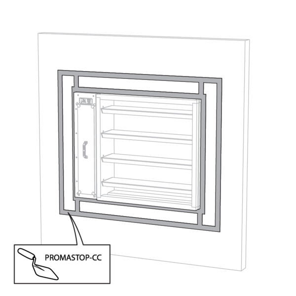
The panels must be installed staggered and the joints must be covered all around with coating (type PROMASTOP-CC) to create a uniform layer thickness for the entire sealing.
Check the functioning of the damper blades after the curing time of the sealing and after removing the struts.
Test the mechanism of the damper.
Test the mechanism of the damper.
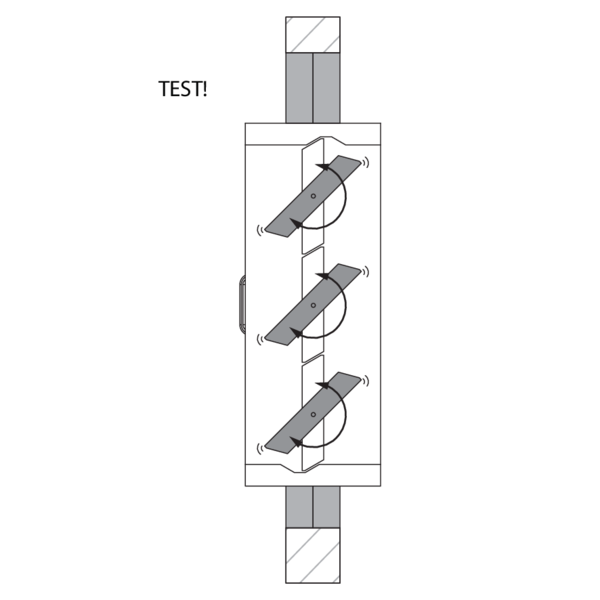
Installation in a rigid wall with collar 1S
The product was tested and approved in:
- Aerated concrete ≥ 100 mm | EI 90/120 (vew i o) S1500 C10000 HOT 400/30 MA MULTI | Not applicable | Type of installation: built-in 0/90/180/270°. In compartment boundary (wall, ‘w’). | 200x200 mm ≤ MARKAGE MB-1S ≤ 1000x1600 mm
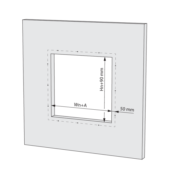
Make an opening with dimensions (Wn+A) x (Hn+90) mm. A = 315 mm for a standard damper. Caution: for a damper with height ≤ 400 mm and option BP FM or ZENiX 1SD, A = 485 mm.
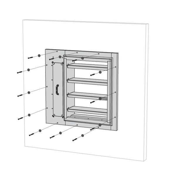
Mount the damper centrally in the opening with the collar against the wall and the collar mounting holes positioned 50 mm from the edge of the opening.
Secure the collar to the wall with the supplied screws Ø 8 x 110 mm and tabs.
Caution: the supplied screws are only suitable for aerated concrete. Use the appropriate type of screws for each wall type: For full bricks: pre-drill with Ø6mm and use the screws and tabs supplied. For compacted concrete: use concrete screws or anchors with characteristic resistance R90...R120 ≥ 0.1kN.
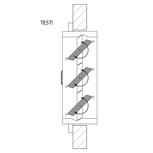
Check the functioning of the damper blades.
Test the mechanism of the damper.
Test the mechanism of the damper.
Installation in rigid floor
The product was tested and approved in:
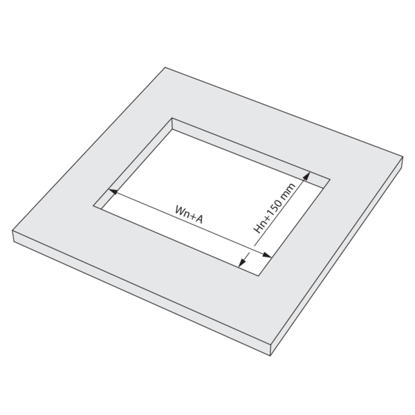
Make an opening with dimensions (Wn+A) x (Hn+150) mm. A = 375 mm for a standard damper. Caution: for a damper with height ≤ 400 mm and option BP FM or ZENiX 1SD, A = 545 mm.
Mount the damper in the opening.
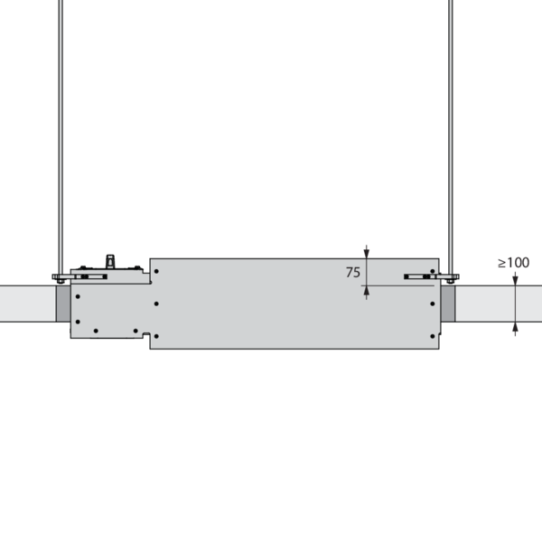
Optionally, the damper can be suspended separately with the horizontal suspension (HS MAS).
Support the tunnel and block the damper blades in the closed position to prevent deformation of the tunnel while the sealing is curing.
Seal the rest of the opening with standard mortar.
Check the functioning of the damper blades after the curing time of the sealing and after removing the struts.
Test the mechanism of the damper.
Test the mechanism of the damper.
Installation in rigid floor, sealing with rigid stone wool boards with coating
The product was tested and approved in:
Make an opening with dimensions (Wn+A+C+D) x (Hn+70+B+E) mm. A = 295 mm for a standard damper. Caution: for a damper with height ≤ 400 mm and option BP FM or ZENiX 1SD, A = 465 mm.
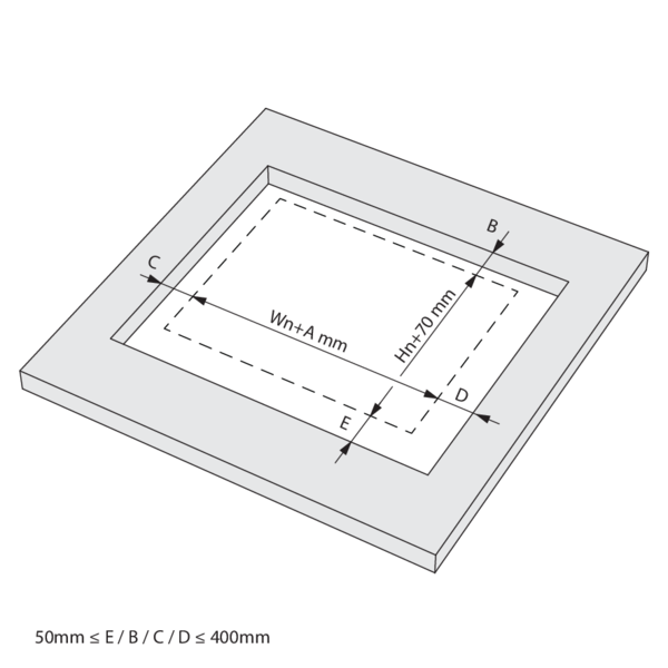
Sealing B, C, D & E between 50 and 400 mm each.
The damper does not need to be centered in the opening. The maximum distance between the damper and the edge of the opening is 400 mm.
The damper does not need to be centered in the opening. The maximum distance between the damper and the edge of the opening is 400 mm.
Mount the damper in the opening.
Bring the damper to the correct height so the seal fits centrally on the damper.
Optionally, the damper can be suspended separately with the horizontal suspension (HS MAS).
Support the tunnel and block the damper blades in the closed position to prevent deformation of the tunnel while the sealing is curing.
Seal the rest of the opening with 2 layers of 50 mm thick coated rigid mineral wool panels (type PROMASTOP CB-CC). The panels must be installed staggered. When installing, always apply coating (type PROMASTOP-CC) to the end of each panel.
The joints must be covered all around with coating (type PROMASTOP-CC) to create a uniform layer thickness for the entire sealing.
Check the functioning of the damper blades after the curing time of the sealing and after removing the struts.
Test the mechanism of the damper.
Test the mechanism of the damper.
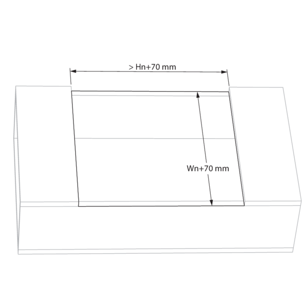
Installation in a horizontal refractory duct, in the plane of the duct
The product was tested and approved in:
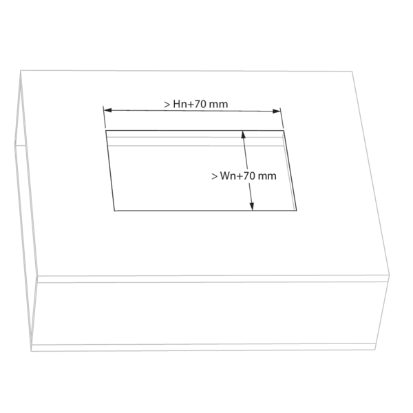
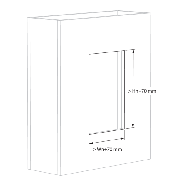
Make an opening with minimum dimensions (Wn+70) x (Hn+70) mm.
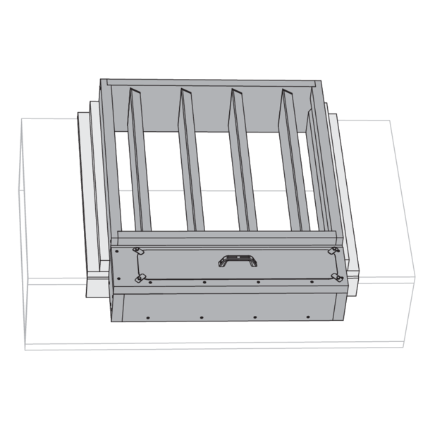
The damper can be mounted directly in this opening.
Fit the damper in the opening with the access hatch accessible. Place the back wall of the damper against the duct.
Installation of the damper does not require a minimum duct depth. The product will not obstruct the airflow in the duct.
Fit the damper in the opening with the access hatch accessible. Place the back wall of the damper against the duct.
Installation of the damper does not require a minimum duct depth. The product will not obstruct the airflow in the duct.
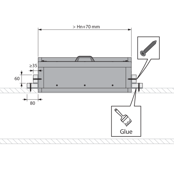
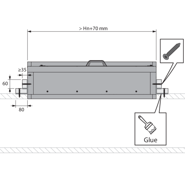
Seal the joint between the damper and the opening with Promat Glue K84. Install the positioning and sealing strips with screws Ø 5 x 50 mm with a maximum spacing of 200 mm and Promat Glue K84. Make sure no screws penetrate the damper casing.
Fabricate the positioning and sealing strips from duct material. For a corner seal, use two strips of 80 mm and 60 mm respectively.
Fabricate the positioning and sealing strips from duct material. For a corner seal, use two strips of 80 mm and 60 mm respectively.
A = 295 mm for a standard damper. Caution: for a damper with height ≤ 400 mm and option BP FM or ZENiX 1SD, A = 465 mm.
Check the functioning of the damper blades after the curing time of the sealing and after removing the struts.
Test the mechanism of the damper.
Test the mechanism of the damper.
Installation in a horizontal refractory duct, overlapping with one side of the duct
The product was tested and approved in:
Make an opening with minimum dimensions (Wn+70) x (Hn+70) mm.
If the opening overlaps with an edge of the duct, follow the installation method below.
If the opening overlaps with an edge of the duct, follow the installation method below.
The damper can be mounted directly in this opening.
If the flanges of the damper coincide with an edge of the duct, make sure they are flush with the duct.
Installation of the damper does not require a minimum duct depth. The product will not obstruct the airflow in the duct.
If the flanges of the damper coincide with an edge of the duct, make sure they are flush with the duct.
Installation of the damper does not require a minimum duct depth. The product will not obstruct the airflow in the duct.
Seal the joint between the damper and the opening with Promat Glue K84. Install the positioning and sealing strips with screws Ø 5 x 50 mm with a maximum spacing of 200 mm and Promat Glue K84. Make sure no screws penetrate the damper casing.
Fabricate the positioning and sealing strips from duct material. For a corner seal, use two strips of 80 mm and 60 mm respectively.
Fabricate the positioning and sealing strips from duct material. For a corner seal, use two strips of 80 mm and 60 mm respectively.
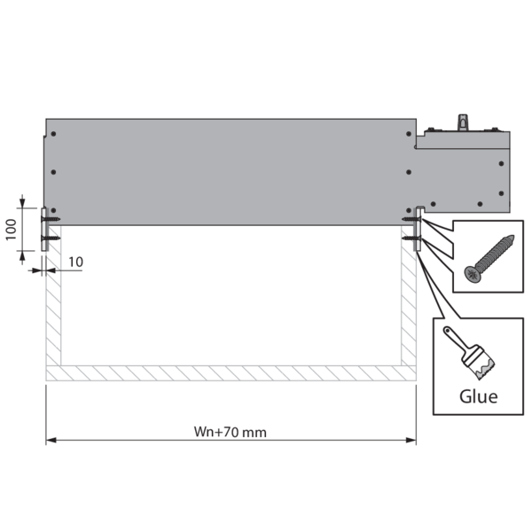
For flat sealing on the flange of the damper, use a strip 10 x 100 mm made from calcium silicate with a density of 870 kg/m³ (type PROMATECT H). Fasten these bars strips two rows of screws Ø 3.9 x 35 mm at intervals of 150 mm.
Check the functioning of the damper blades after the curing time of the sealing and after removing the struts.
Test the mechanism of the damper.
Test the mechanism of the damper.
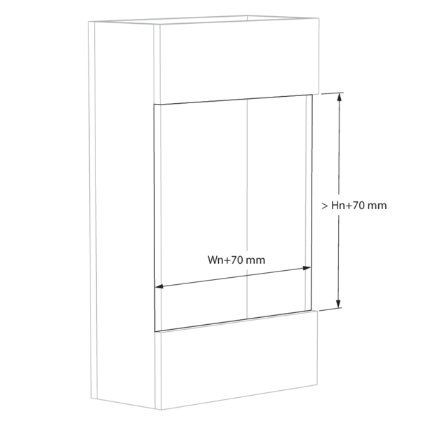
Installation in a vertical refractory duct or in the vertical plane of a horizontal duct, within the plane of the duct
The product was tested and approved in:
Make an opening with minimum dimensions (Wn+70) x (Hn+70) mm.

Optionally, the damper can be suspended separately with the vertical suspension (VS MAS).

The damper can be mounted directly in this opening.
Fit the damper in the opening with the access hatch accessible. Place the back wall of this compartment against the duct.
Installation of the damper does not require a minimum duct depth. The product will not obstruct the airflow in the duct.
A = 295 mm for a standard damper. Caution: for a damper with height ≤ 400 mm and option BP FM or ZENiX 1SD, A = 465 mm.

Seal the joint between the damper and the opening with Promat Glue K84. Install the positioning and sealing strips with screws Ø 5 x 50 mm with a maximum spacing of 200 mm and Promat Glue K84. Make sure no screws penetrate the damper casing.
Fabricate the positioning and sealing strips from duct material. For a corner seal, use two strips of 80 mm and 60 mm respectively.
Fabricate the positioning and sealing strips from duct material. For a corner seal, use two strips of 80 mm and 60 mm respectively.
Check the functioning of the damper blades after the curing time of the sealing and after removing the struts.
Test the mechanism of the damper.
Test the mechanism of the damper.
Installation in a vertical refractory duct, overlapping with one side of the duct
The product was tested and approved in:
Make an opening with minimum dimensions (Wn+70) x (Hn+70) mm.
If the opening overlaps with an edge of the duct, follow the installation method below.
If the opening overlaps with an edge of the duct, follow the installation method below.

Optionally, the damper can be suspended separately with the vertical suspension (VS MAS).
The damper can be mounted directly in this opening.
Fit the damper in the opening with the access hatch accessible.
The back wall of the damper is placed against the duct if it does not extend outside the duct.
If the flanges of the damper coincide with an edge of the duct, make sure they are flush with the duct.
Installation of the damper does not require a minimum duct depth. The product will not obstruct the airflow in the duct.

Seal the joint between the damper and the opening with Promat Glue K84. For flat sealing on the flange of the damper, use a strip 10 x 100 mm made from calcium silicate with a density of 870 kg/m³ (type PROMATECT H). Fasten these strips with two rows of screws Ø 3.9 x 35 mm at intervals of 150 mm.

Install the positioning and sealing strips with screws Ø 5 x 50 mm with a maximum spacing of 200 mm and Promat Glue K84. Make sure no screws penetrate the damper casing.
Fabricate the positioning and sealing strips from duct material. For a corner seal, use two strips of 80 mm and 60 mm respectively.
Fabricate the positioning and sealing strips from duct material. For a corner seal, use two strips of 80 mm and 60 mm respectively.
Check the functioning of the damper blades after the curing time of the sealing and after removing the struts.
Test the mechanism of the damper.
Test the mechanism of the damper.
Installation in the vertical plane of a horizontal refractory duct, overlapping with one side of the duct
The product was tested and approved in:

Make an opening with minimum dimensions (Wn+70) x (Hn+70) mm.
If the opening overlaps with an edge of the duct, follow the installation method below.
If the opening overlaps with an edge of the duct, follow the installation method below.

Optionally, the damper can be suspended separately with the vertical suspension (VS MAS).
The damper can be mounted directly in this opening.
Fit the damper in the opening with the access hatch accessible.
The back wall of the damper is placed against the duct if it does not extend outside the duct.
If the flanges of the damper coincide with an edge of the duct, make sure they are flush with the duct.
Installation of the damper does not require a minimum duct depth. The product will not obstruct the airflow in the duct.
The damper can be mounted directly in this opening.
Fit the damper in the opening with the access hatch accessible.
The back wall of the damper is placed against the duct if it does not extend outside the duct.
If the flanges of the damper coincide with an edge of the duct, make sure they are flush with the duct.
Installation of the damper does not require a minimum duct depth. The product will not obstruct the airflow in the duct.

Seal the joint between the damper and the opening with Promat Glue K84. Install the positioning and sealing strips with screws Ø 5 x 50 mm with a maximum spacing of 200 mm and Promat Glue K84. Make sure no screws penetrate the damper casing.
Fabricate the positioning and sealing strips from duct material. For a corner seal, use two strips of 80 mm and 60 mm respectively.
A = 295 mm for a standard damper. Caution: for a damper with height ≤ 400 mm and option BP FM or ZENiX 1SD, A = 465 mm.
Fabricate the positioning and sealing strips from duct material. For a corner seal, use two strips of 80 mm and 60 mm respectively.
A = 295 mm for a standard damper. Caution: for a damper with height ≤ 400 mm and option BP FM or ZENiX 1SD, A = 465 mm.

For flat sealing on the flange of the damper, use a strip 10 x 100 mm made from calcium silicate with a density of 870 kg/m³ (type PROMATECT H). Fasten these bars strips two rows of screws Ø 3.9 x 35 mm at intervals of 150 mm.
Check the functioning of the damper blades after the curing time of the sealing and after removing the struts.
Test the mechanism of the damper.
Test the mechanism of the damper.
Installation in shaftwall, sealing with mortar
The product was tested and approved in:
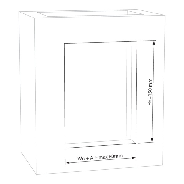
Make an opening with dimensions (Wn + A + max 80mm) x (Hn + 150mm). A = 295 mm for a standard damper. Attention: for a damper ≤ 400 mm high and with option BP FM or ZENiX 1SD, A = 465 mm.
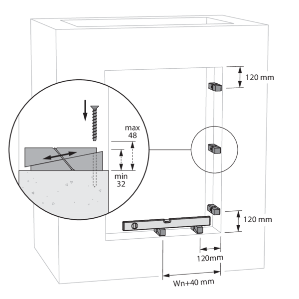
Optionally, the damper can be placed in the centre of the opening using the KITS SUPP.
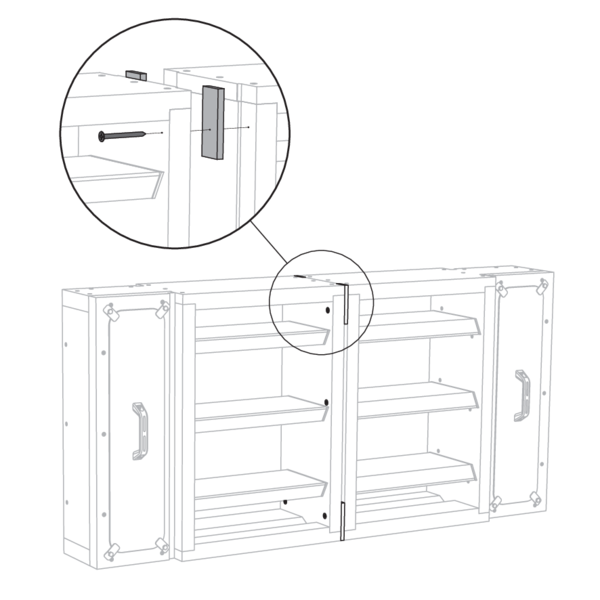
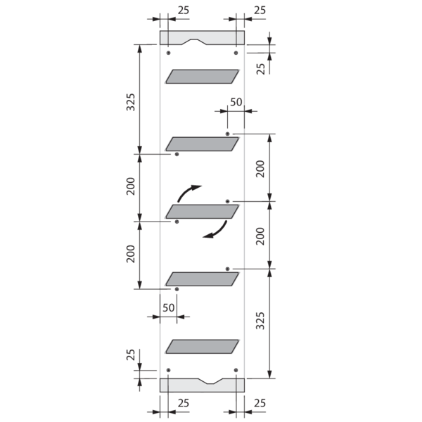
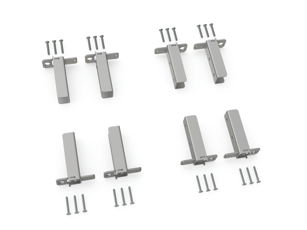
Place elements of the KITS SUPP in the opening at the indicated distances. Attach each element by gluing or screwing it in the reveal.
Attention: ensure that both wedges of each KITS SUPP element remain moveable relative to each other.
Use a water level for placement of the damper. The height can be adjusted by moving each element of the KITS SUPP. Set up a straight angle by aligning the elements of the KITS SUPP with the vertical reveal.
Attention: the elements of the KITS SUPP are not found in the actuator compartment of the damper.
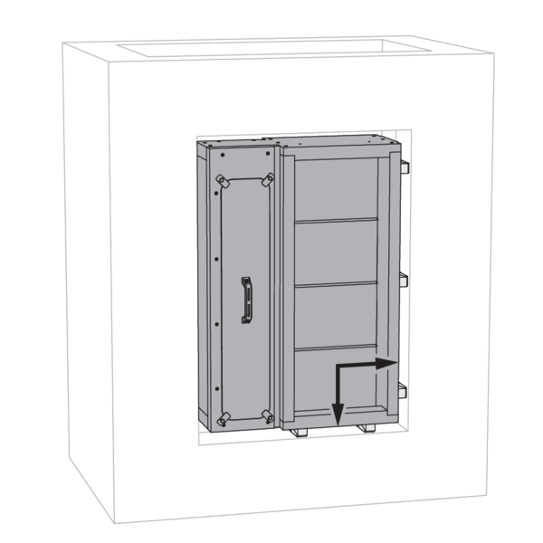
Place the damper in the opening. Align the damper with the elements of the KITS SUPP if present.
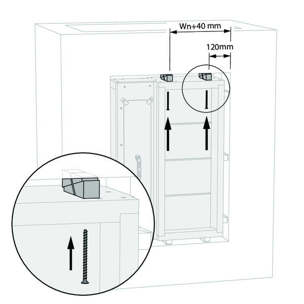
Add elements of the KITS SUPP to the remaining side at the indicated distances. Eliminate the slack between the wall and the damper by moving both wedges of each KITS SUPP element relative to each other.
Optionally, anchor the damper inside the wall using a suitable screw type for that wall type. Drill through both the tunnel wall and the elements of the KITS SUPP.
Attention: Make sure no screws protrude that may hinder the rotation of the damper blades. When placing the screws, mind the rotational direction of the damper blades if possible.
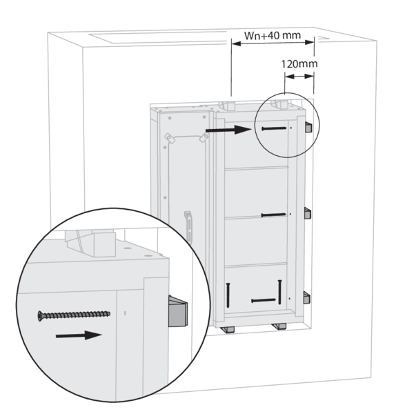
Drill through both the tunnel wall and the elements of the KITS SUPP to place any additional anchoring. Ensure that any slack between the tunnel wall and the reveal is completely filled by the elements of the KITS SUPP.
Attention: Make sure no screws protrude that may hinder the rotation of the damper blades. When placing the screws, mind the rotational direction of the damper blades if possible.
Attention: Make sure no screws protrude that may hinder the rotation of the damper blades. When placing the screws, mind the rotational direction of the damper blades if possible.
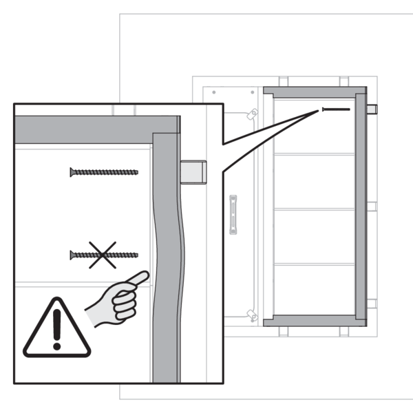
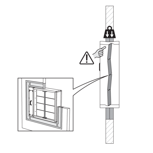
Attention: Anchoring of the damper without KITS SUPP may seriously damage the product. If anchor screws are tightened without support at the joint level, the tunnel wall may deform and break.
Support the tunnel and block the damper blades in the closed position to prevent deformation of the tunnel while the sealing is curing.
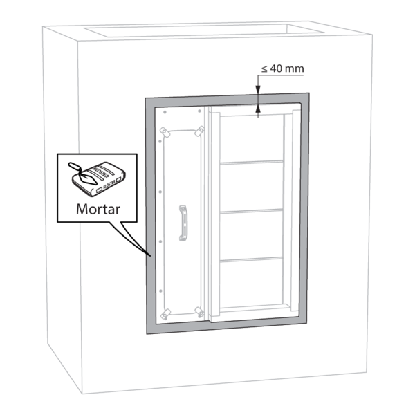
Seal the rest of the opening with standard mortar.
Check the functioning of the damper blades after the curing time of the sealing and after removing the struts.
Test the mechanism of the damper.
Test the mechanism of the damper.
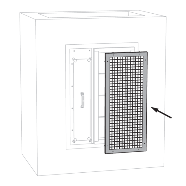
Finish the installation. Place a grille to prevent direct contact with the damper blades.
Installation in a refractory duct, in the cross-section of the duct
The product was tested and approved in:

Place the damper in the middle of the duct with external dimensions (Wn + 70) x (Hn + 70) mm. The damper can be suspended separately with the vertical suspension (VS MAS). Analogously, the horizontal suspension (HS MAS) can be used with a vertical duct.

Seal the joint between the damper and the opening with Promat Glue K84. For flat sealing on the flange of the damper, use a strip 10 x 100 mm made from calcium silicate with a density of 870 kg/m³ (type PROMATECT H). Fasten these strips with two rows of screws Ø 3.9 x 35 mm at intervals of 150 mm.

Finish the sealing completely.
Check the functioning of the damper blades after the curing time of the sealing and after removing the struts.
Test the mechanism of the damper.
Test the mechanism of the damper.
Installation in a refractory duct, at the end of the duct
The product was tested and approved in:

Place the damper in the middle of the duct with external dimensions (Wn + 70) x (Hn + 70) mm. The damper can be suspended separately with the vertical suspension (VS MAS). Analogously, the horizontal suspension (HS MAS) can be used with a vertical duct.

Seal the joint between the damper and the opening with Promat Glue K84. For flat sealing on the flange of the damper, use a strip 10 x 100 mm made from calcium silicate with a density of 870 kg/m³ (type PROMATECT H). Fasten these strips with two rows of screws Ø 3.9 x 35 mm at intervals of 150 mm.

Finish the sealing completely.
Check the functioning of the damper blades after the curing time of the sealing and after removing the struts.
Test the mechanism of the damper.
Place a grille (PPT) on the damper to protect the damper blades.
Test the mechanism of the damper.
Place a grille (PPT) on the damper to protect the damper blades.
Battery mounting with option JK BAT
For battery mounting with the damper blades in line with each other:
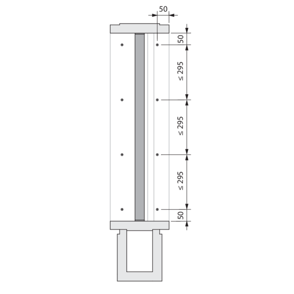
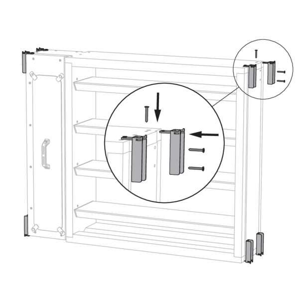
Install both dampers against one another with the connection compartments on opposite sides.
Install the calcium silicate plates at the end of each groove between both dampers. Make sure the plates are flush with the damper connection flanges.
Install both dampers against one another with the connection compartments on opposite sides.
Install the calcium silicate plates at the end of each groove between both dampers. Make sure the plates are flush with the damper connection flanges.
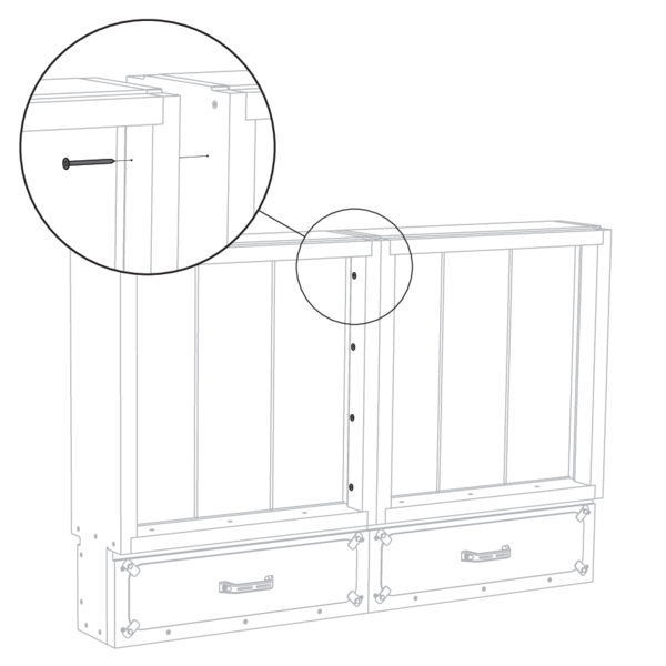
Attach one damper to the other with the supplied screws Ø 5 x 70 mm. Pay attention to the rotation direction of the damper blades and ensure that the screws do not interfere with the damper blades.
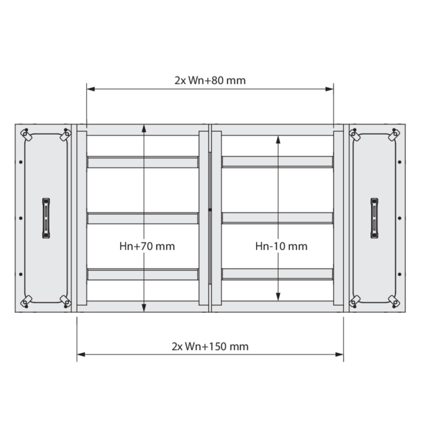
The collar with external dimensions ((2 x Wn) +150) mm x (Hn + 70) mm is suitable for connecting a common duct.
No JK BAT-kit required for battery mounting with the connection compartments in line with each other:
Install both dampers against one another with the connection compartments aligned.
Install both dampers against one another with the connection compartments aligned.
Attach one damper to the other with screws Ø 5 x 70 mm on both the front and back of the dampers.
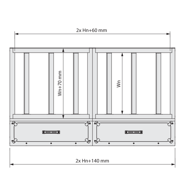
The collar with external dimensions ((2 x Wn) +140) mm x (Hn + 70) mm is suitable for connecting a common duct.
Check the functioning of the damper blades after the curing time of the sealing and after removing the struts.
Test the mechanism of the damper.
Test the mechanism of the damper.
Installation with vertical suspension (VS MAS)
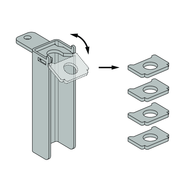
Break off the tabs of the angle brackets and save them for further installation.
Fit the angle brackets on the corners of the damper.
The orientation depends on the desired orientation of the damper (vertical or horizontal damper blades).
Align the U-profiles of the angle brackets with one another and note the vertical direction. The short side of each angle bracket, with one screw, should be on the top or bottom of the damper.
The orientation depends on the desired orientation of the damper (vertical or horizontal damper blades).
Align the U-profiles of the angle brackets with one another and note the vertical direction. The short side of each angle bracket, with one screw, should be on the top or bottom of the damper.
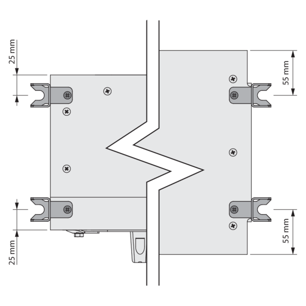
Attach the angle brackets with the supplied screws Ø 5x35 mm. The screws near the connection compartment are 25 mm from the edge, while screws in the tunnel wall are 55 mm from the edge.
Position the damper in the opening of the wall according to the guidelines for each wall type.
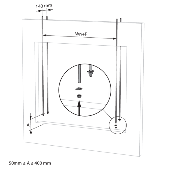
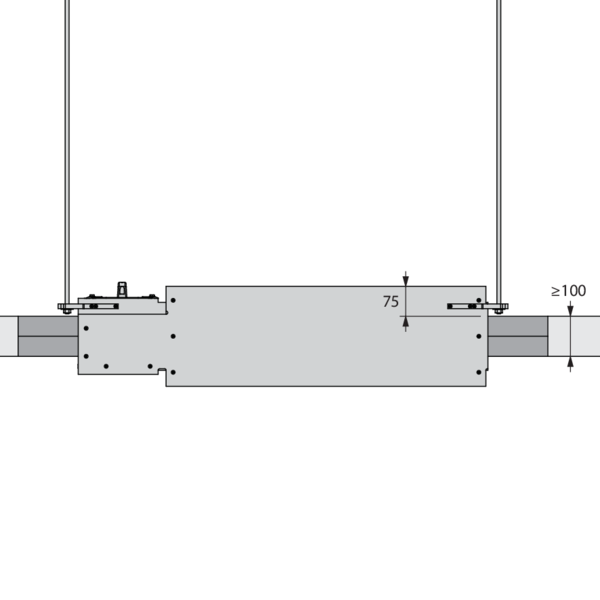
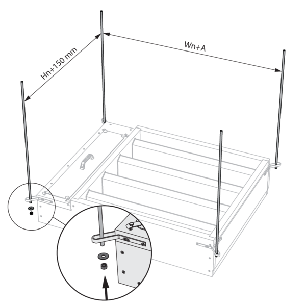
Fit the threaded rods (≥ M10) for damper suspension on the front and back of the wall, with F = 320 mm for a standard damper. Caution: for a damper with height ≤ 400 mm and option BP FM or ZENiX 1SD, F = 490 mm. Put a tab and a nut on each threaded rod. Align all tabs at the same height.
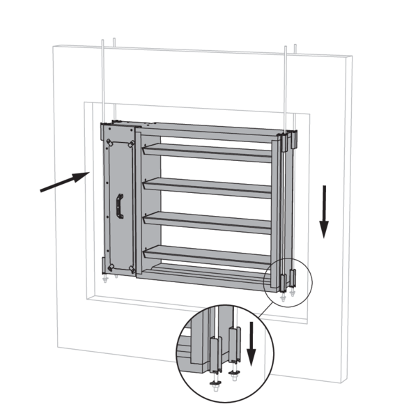
Place the damper on the tabs. The threaded rods must be inside the U profiles of the angle brackets. Make sure to secure the tabs to the bottom angle brackets.
When passing through the compartment wall, the suspension must not be insulated. When installed in ducts, the suspension must be insulated in the same way as the suspension of the duct.
When passing through the compartment wall, the suspension must not be insulated. When installed in ducts, the suspension must be insulated in the same way as the suspension of the duct.
Support the tunnel and block the damper blades in the closed position to prevent deformation of the tunnel while the sealing is curing.
Complete the sealing of the damper according to the guidelines per wall type.
Complete the sealing of the damper according to the guidelines per wall type.
Installation with horizontal suspension (HS MAS)
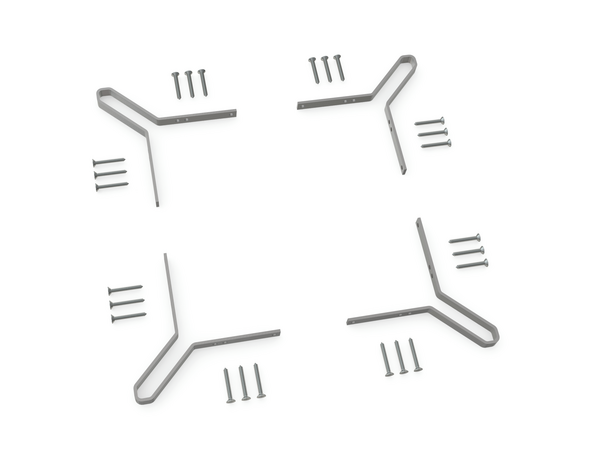
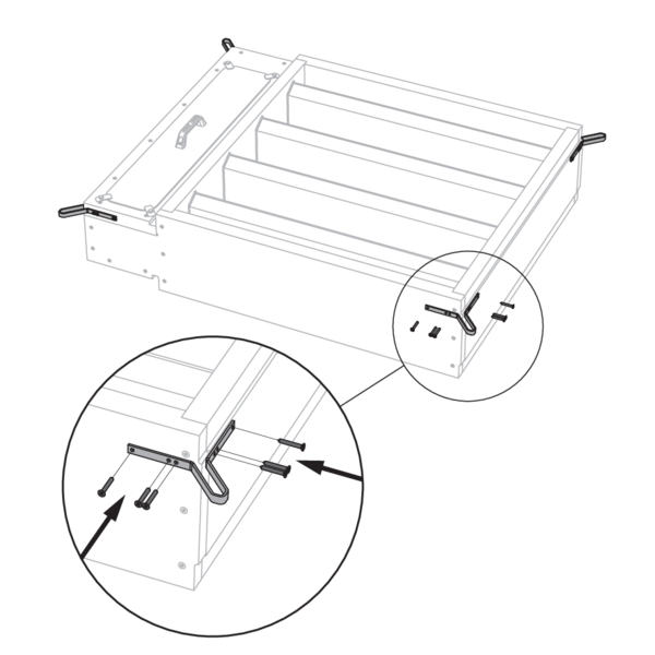
Fit the angle brackets on the corners of the damper.
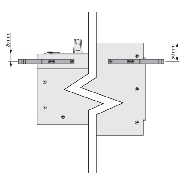
Attach the angle brackets with the supplied screws Ø 5x35 mm. The screws near the connection compartment are 20 mm from the edge, while screws in the tunnel wall are 50 mm from the edge.
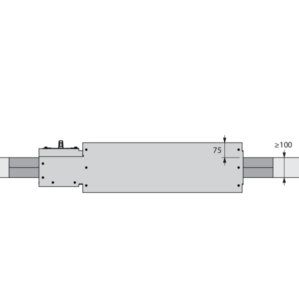
Fit the threaded rods (≥ M10) for damper suspension, with A = 375 mm for a standard damper. Caution: for a damper with height ≤ 400 mm and option BP FM or ZENiX 1SD, A = 545 mm. Position the damper and place a tab and a nut on each threaded rod for fastening.
Complete the sealing of the damper according to the guidelines per wall type.
Complete the sealing of the damper according to the guidelines per wall type.
General remarks
- The installation must comply with the installation manual and the classification report.
- The installation of the smoke control duct must comply with the classification report delivered by the manufacturer.
- Axis orientation: see the declaration of performance.
- Avoid the obstruction of adjoining smoke control ducts.
- Verify if the blade can move freely.
- Rf-t smoke dampers may be applied to smoke control ducts that have been tested according to EN 1366-8 and EN 1366-9 as appropriate.
- Caution: when fitting, the product should be handled with care and remain protected from any sealing products.
- Caution: before putting the installation into operation, clean off all the dust and dirt.
- Caution: bear in mind the blade’s clearance inside the smoke control duct.