SC-S - Installation
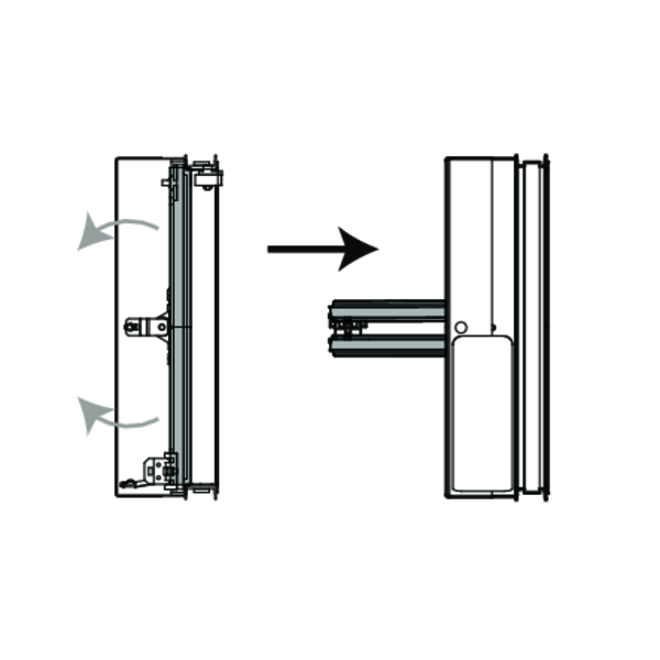
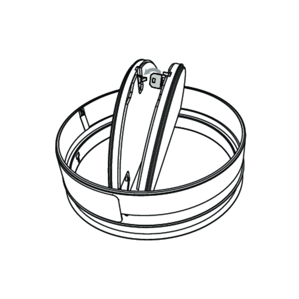
Operation: manual closing
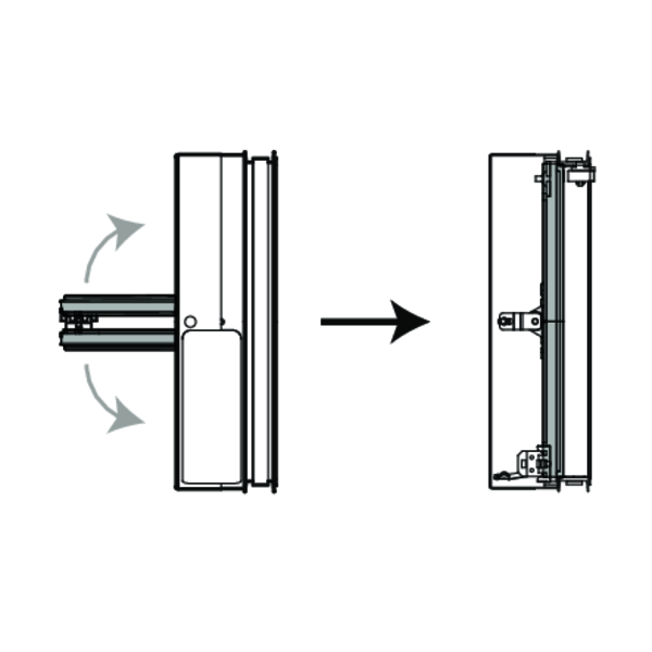
Unlock (close) the damper blades by pushing them towards each other. Carefully unlock the fusible link by pushing it sidewards.
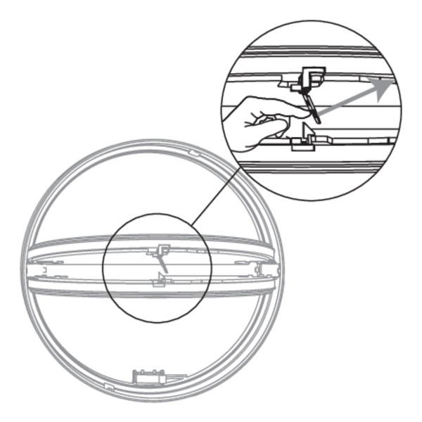
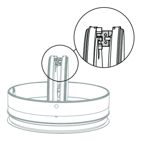
Operation: manual opening
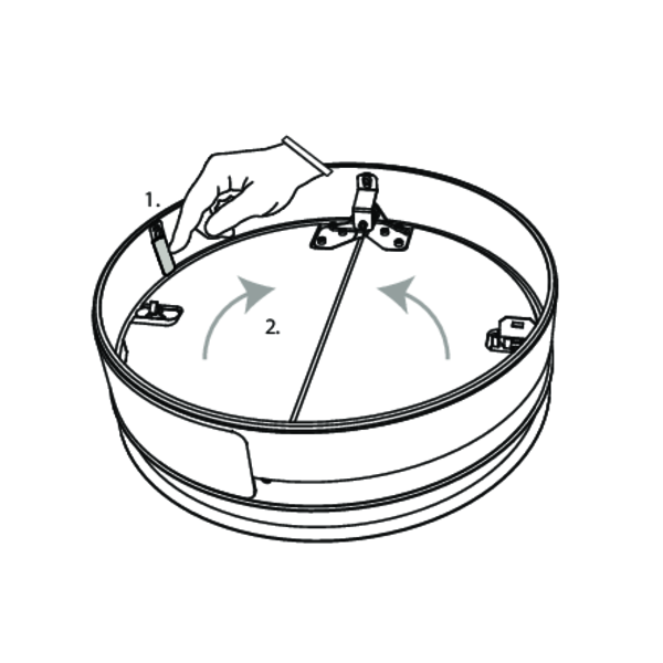
Press the two blocking hooks carefully to unlock the blades.
Click the fusible link into the holder to lock the blades.
Installation in a fire resistant suspended ceiling
The product was tested and approved in:
- Metal studs gypsum plasterboard Type F (EN 520) 2 x 12.5 mm | EI 30 (ho o i) S - (300Pa) | Not applicable | Type of installation: built-in inside a duct, 0-360°; Fire side = side opposite to the fusible link | SC-S Ø 100-200 mm
- Metal studs gypsum plasterboard Type F (EN 520) 2 x 15 mm | EI 60 (ho o i) S - (300Pa) | Not applicable | Type of installation: built-in inside a duct, 0-360°; Fire side = side opposite to the fusible link | SC-S Ø 100-200 mm
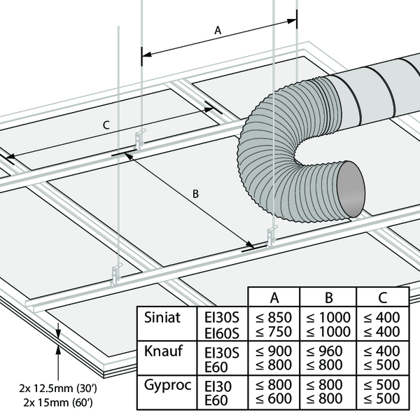
Build the fire resistant suspended ceiling according to the manufacturer's instructions. Provide a piece a flexible duct to connect the ventilation duct to the SC-S.
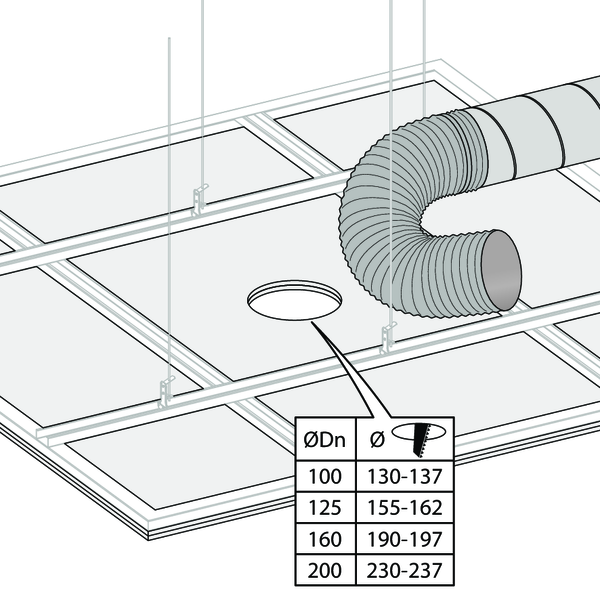
Make a round opening in the fire resistant suspended ceiling, with diameter as indicated in the table.
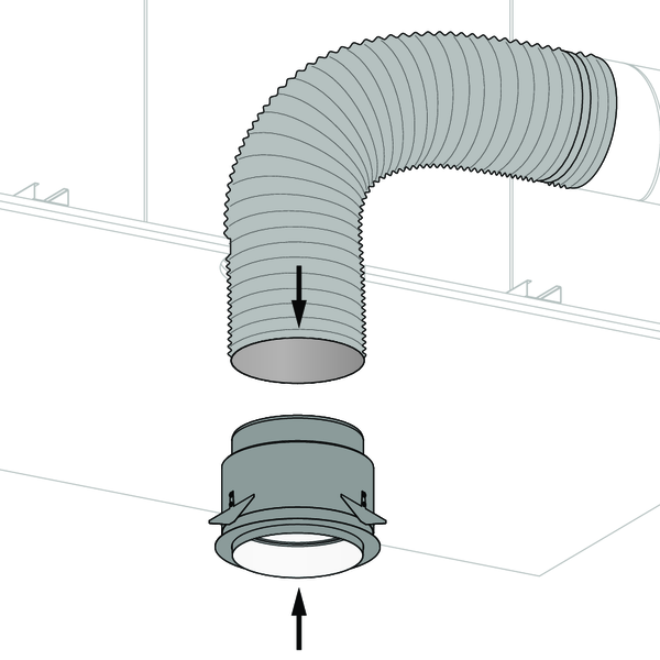
Arm the fire damper cartridge as explained in the operating instructions. Pull the flexible duct through the opening and place it over the connection provided for the ventilation duct. Attach the duct to the SC-S in an airtight manner.
Caution: Make sure the damper blades are in open position before installing into the ceiling.
Caution: Make sure the damper blades are in open position before installing into the ceiling.
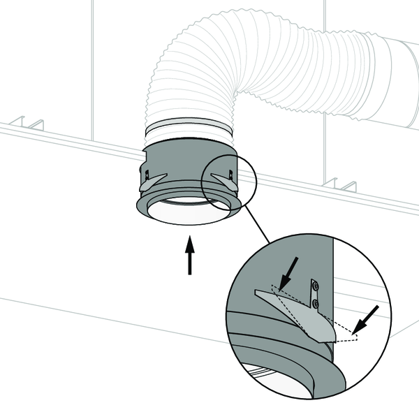
Press the retaining springs against the cylinder and slide the SC-S in the opening. Push the SC-S all the way into the opening so that the retaining springs lock above the ceiling.
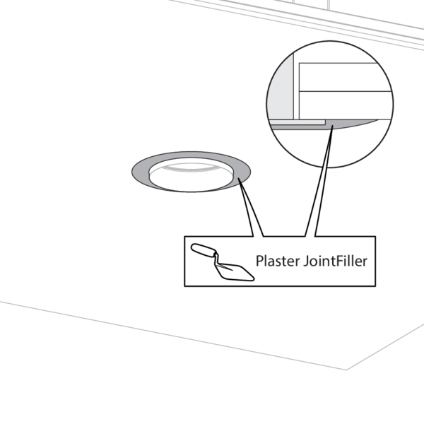
Finish with joint filler and allow to dry.
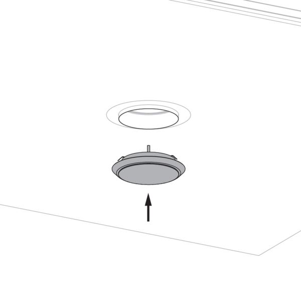
Finally, install the finishing valve and adjust according to the desired flow rate.
The use of another plastic finishing valve is permitted, as long as it does not interfere with the operation of the damper blades.
The use of another plastic finishing valve is permitted, as long as it does not interfere with the operation of the damper blades.
General remarks
- Verify if the blade can move freely.
- The fire damper cartridge must remain accessible for inspection and maintenance.
- Please observe safety distances with respect to other construction elements.
Product-specific remarks
- The installation must comply with the installation manual.
- SC-S fire damper cartridges are tested in standardised fire resistant suspended ceilings in accordance with EN 1366-2 and EN 1364-2.
- Direction of the airflow: discretionary
- If the product is manipulated in any other way than described in this manual, Rf-Technologies will decline any responsibility and the guarantee will expire!
- Do not hold the SC-S by the finishing collar.