SC+60 - Installation
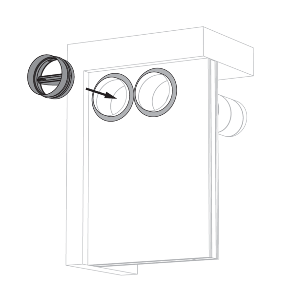
Operation: manual opening
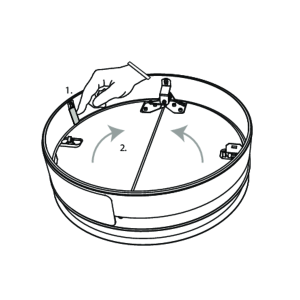
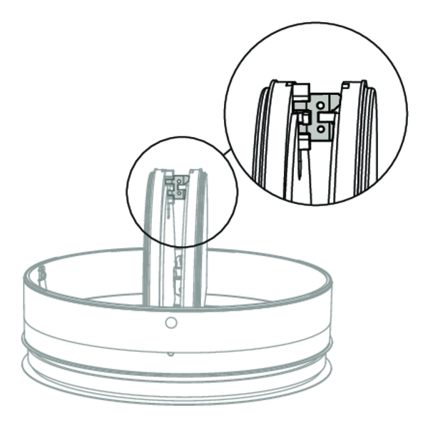
Press the two blocking hooks carefully to unlock the blades.
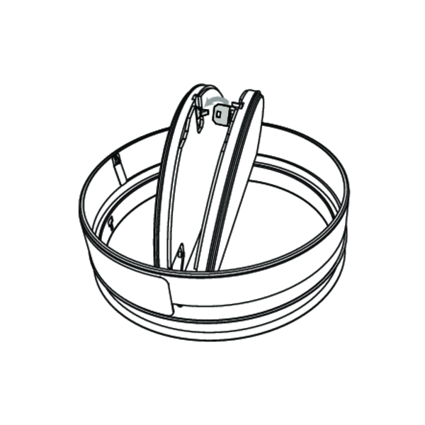
Click the fusible link into the holder to lock the blades.
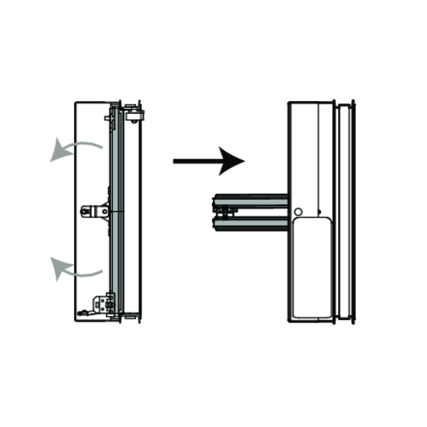
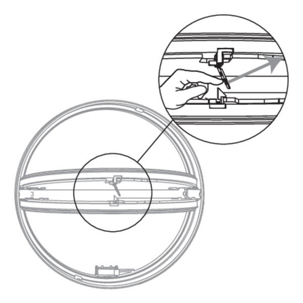
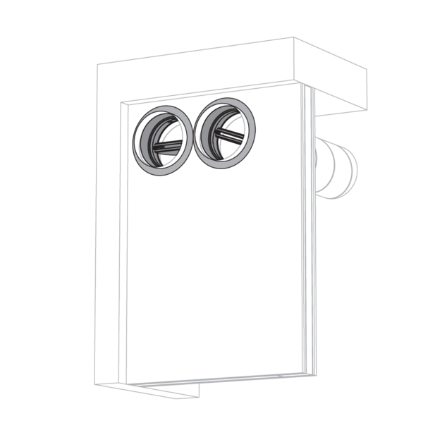
Operation: manual closing
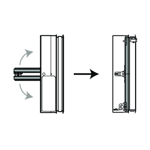
Unlock (close) the damper blades by pushing them towards each other. Carefully unlock the fusible link by pushing it sidewards.
Electrical wiring
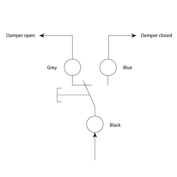
An end of range switch (FCU) can be mounted on the metal body. The purpose is to determine the position of the circular fire damper cartridge from a distance. 1mA...6A DC 5V....AC250V.
COM: black; NF: grey; NO: blue.
Power supply: Max 250V; Power consumption : Max 6A; Degree of protection: IP65; Length of cable: 500 mm.
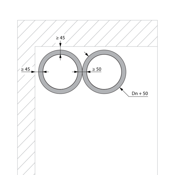
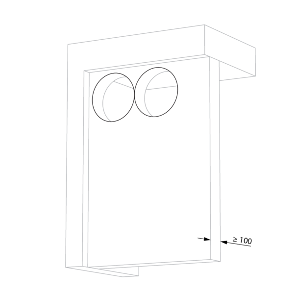
Installation at a minimal distance from another damper or from an adjacent supporting construction
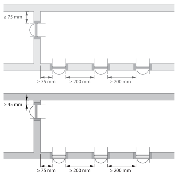
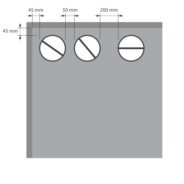
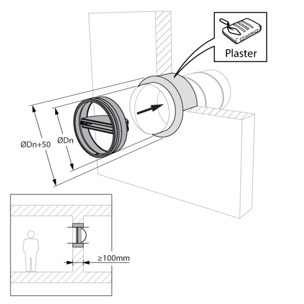
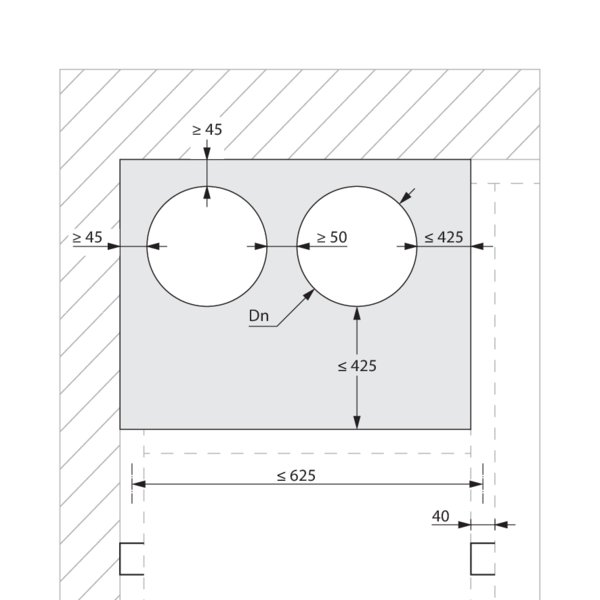
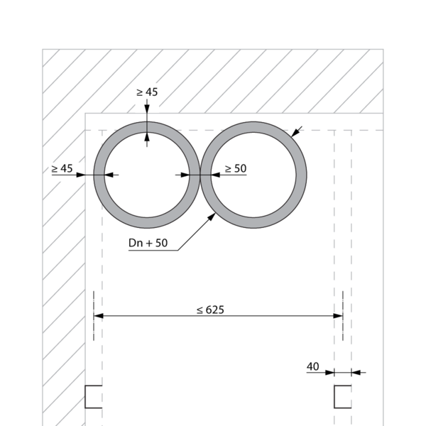
According to the European test standard, a fire damper must be installed at a minimum distance of 75 mm from an adjacent wall and 200 mm from another damper, unless the solution was tested at a shorter distance.
This range of Rf-t fire dampers has been successfully tested and in several installation methods can be installed in a vertical supporting construction, at a distance below the minimum set by the standard - see below.
If installation at a shorter distance (only possible for certain installation methods) take in account following restriction:
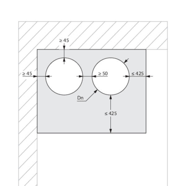
A maximum of 2 circular dampers can be installed horizontally at a minimum distance from one another.
A maximum of 2 circular dampers can be installed horizontally at a minimum distance from one another.
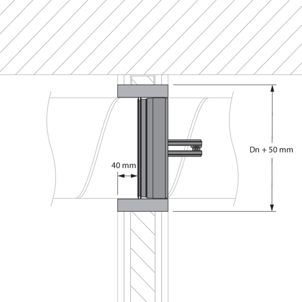
Installation in rigid wall, sealing with rigid stone wool boards with coating - SC+60
The product was tested and approved in:
- Aerated concrete ≥ 100 mm | EI 60 (ve i o) S - (300Pa) | Stone wool + coating ≥ 140 kg/m³ | Type of installation: built-in inside a duct, 0-360°. Minimal distances authorised. | SC+60 Ø 100-200 mm
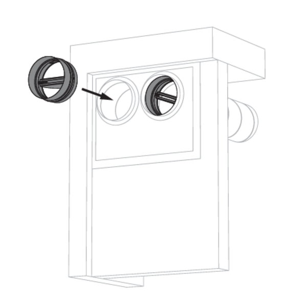
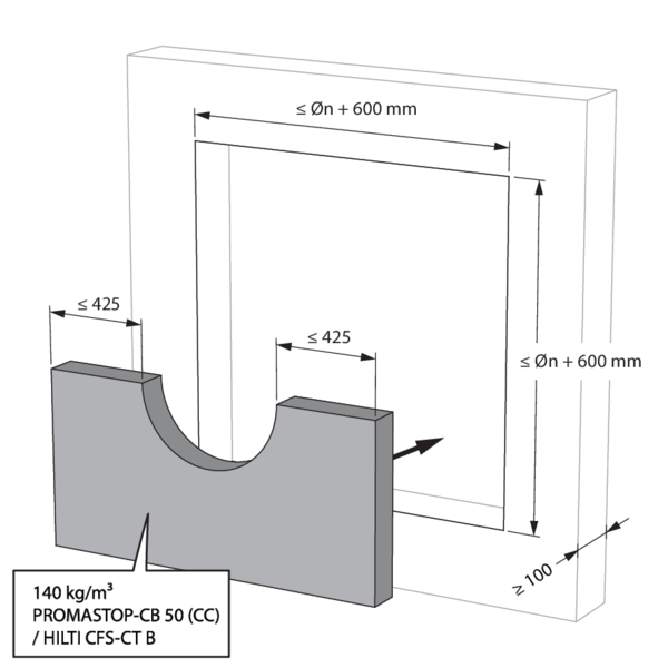
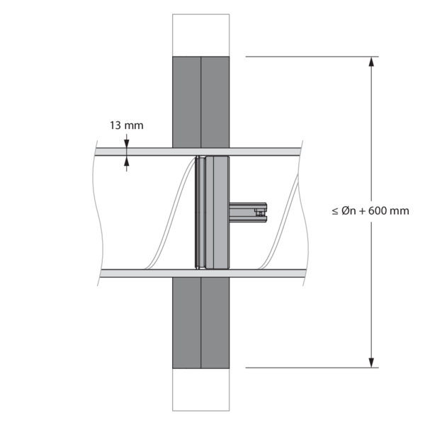
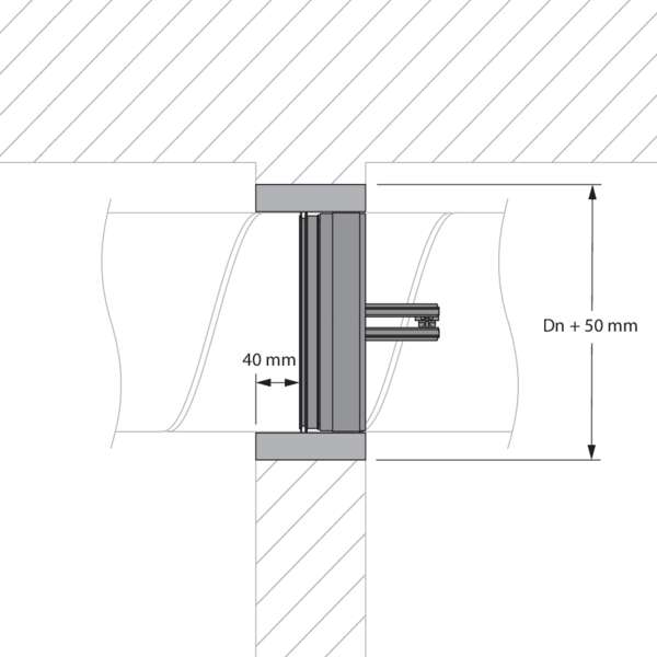
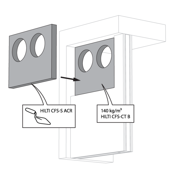
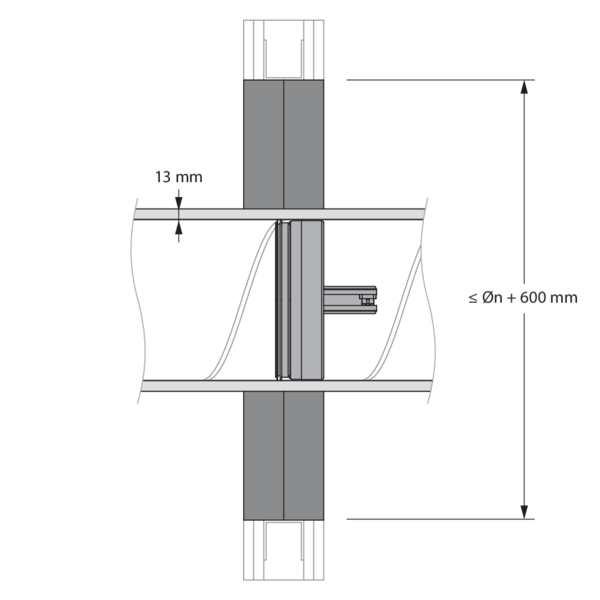
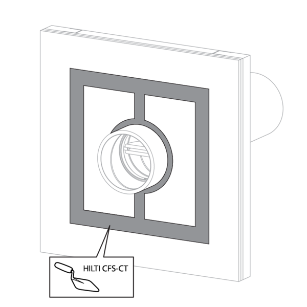
The opening in the wall around the duct in which the fire damper cartridge is mounted, is sealed with 2 layers of 50 mm-thick stone wool panels with fire resistant coating on one side (type HILTI CFS-CT B).
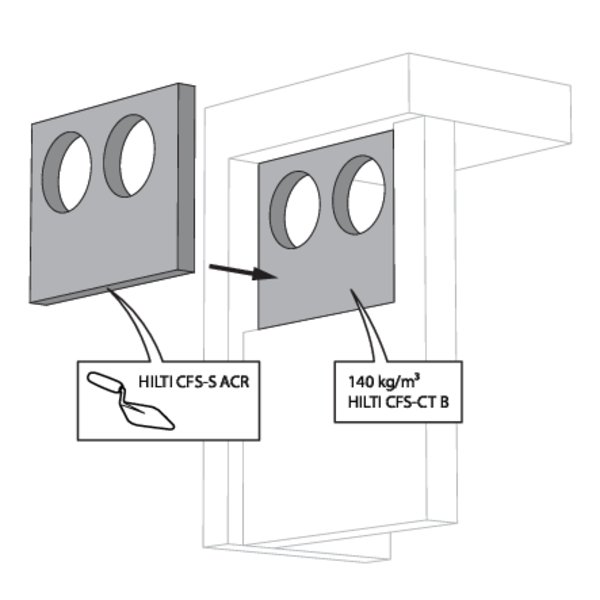
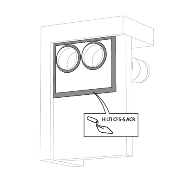
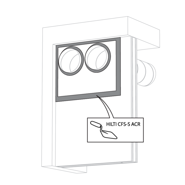
The joints on these 2 layers must be installed staggered and covered all around the edge with coating (type HILTI CFS-S-ACR).
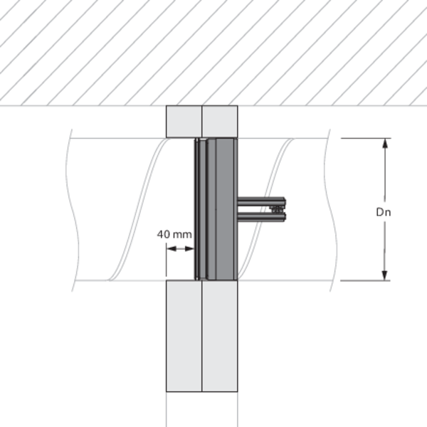
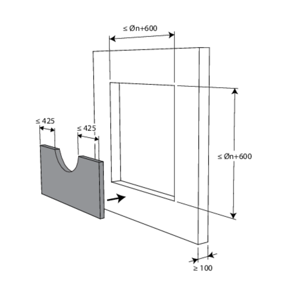
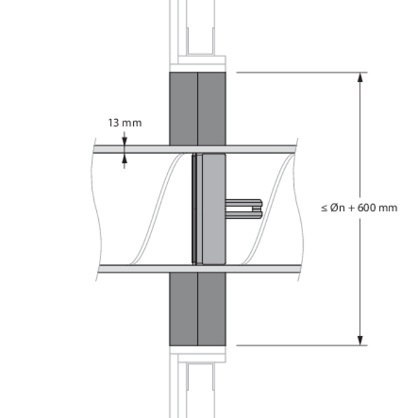
The duct in which the damper is inserted doesn't need be centered in the opening (with max dimensions duct + 600 mm). The maximal distance between the damper and the edge of the opening is 425 mm.
Installation in rigid wall, insulated duct, sealing with rigid stone wool boards with coating - SC+60
The product was tested and approved in:
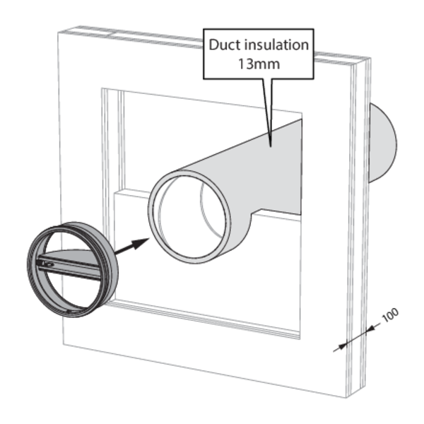
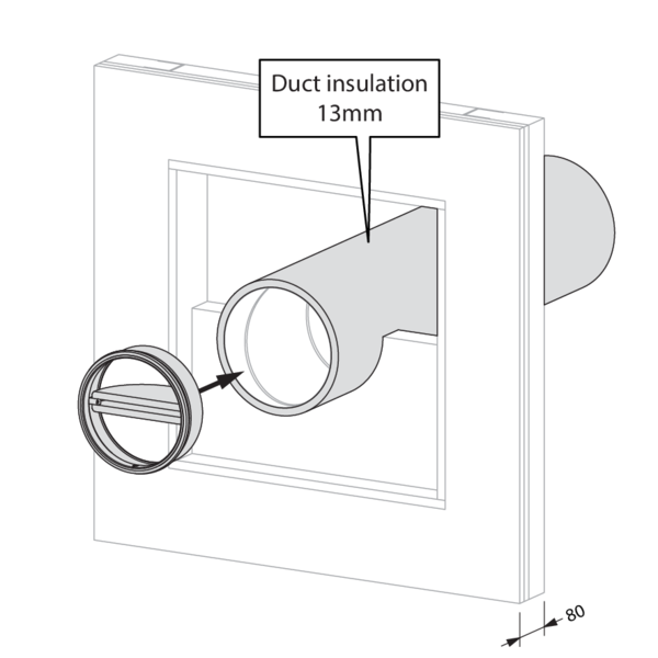
- Aerated concrete ≥ 100 mm | EI 60 (ve i o) S - (300Pa) | Insulated duct (ArmaFlex EVO, ArmaFlex Protect – up to 13 mm) + stone wool + coating ≥ 140 kg/m³ | Type of installation: built-in inside a duct, 0-360° | SC+60 Ø 100-200 mm
The fire batt type Hilti CFS-CT B may be replaced by a similar type of fire batt with at least the same fire reaction class, density and thickness (tested according to EN 1366-3), for example PROMASTOP-CB 50 (CC).
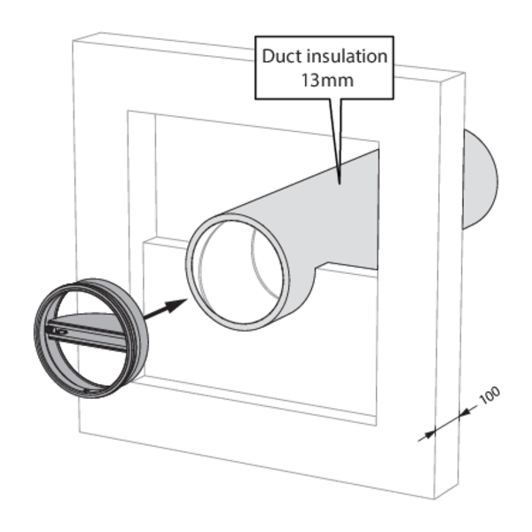
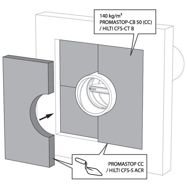
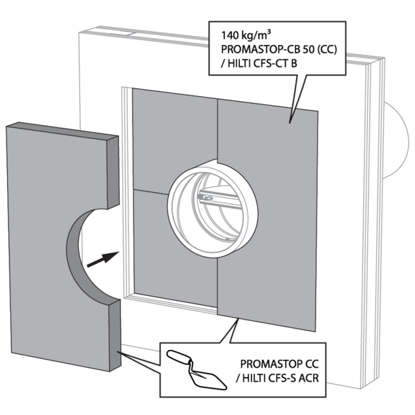
The opening in the wall around the insulated duct, is sealed with 2 rigid stone wool boards of 50 mm with fire-resistant coating on one side (type PROMASTOP-CB50 / Hilti CFS-CT B).
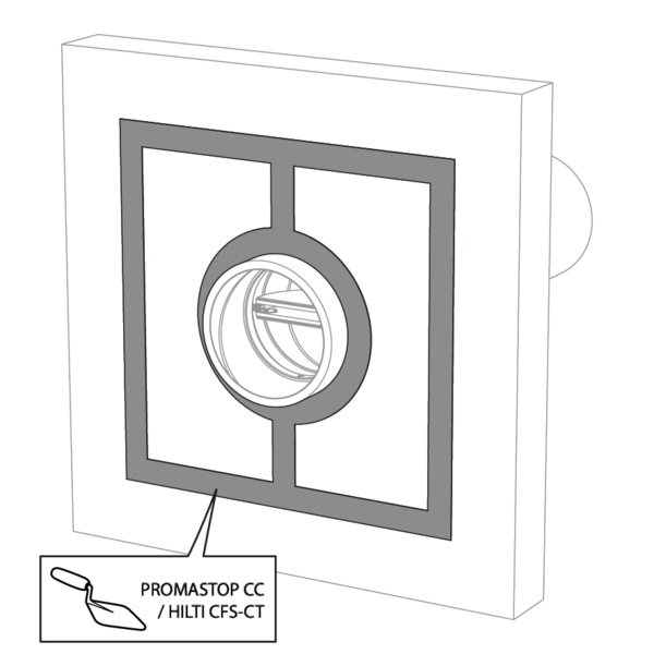
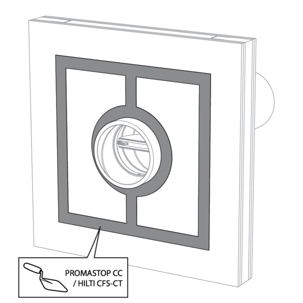
The joints on these 2 layers must be installed staggered and covered all around the edge with coating (type PROMASTOP-CC / HILTI CFS-S-ACR).
Installation in rigid wall with gypsum sealing - SC+60
The product was tested and approved in:
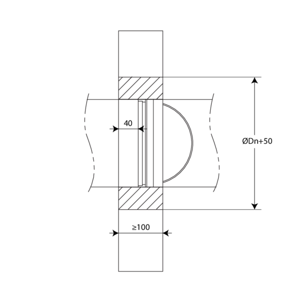
- Aerated concrete ≥ 100 mm | EI 60 (ve i o) S - (300Pa) | Gypsum | Type of installation: built-in inside a duct, 0-360°. Minimal distances authorised. | SC+60 Ø 100-200 mm
Installation in flexible wall, sealing with rigid stone wool boards with coating - SC+60
The product was tested and approved in:
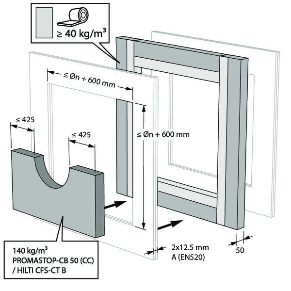
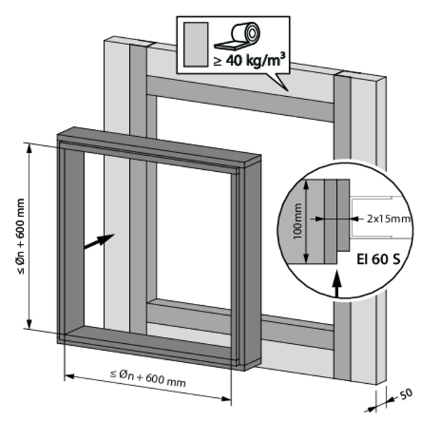
- Metal studs gypsum plasterboard Type A (EN 520) ≥ 100 mm | EI 60 (ve i o) S - (300Pa) | Stone wool + coating ≥ 140 kg/m³ | Type of installation: built-in inside a duct, 0-360°. Minimal distances authorised. | SC+60 Ø 100-200 mm
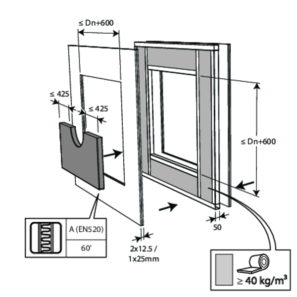
The opening in the wall around the duct in which the fire damper cartridge is mounted, is sealed with 2 layers of 50 mm-thick stone wool panels with fire resistant coating on one side (type HILTI CFS-CT B).
The joints on these 2 layers must be installed staggered and covered all around the edge with coating (type HILTI CFS-S-ACR).
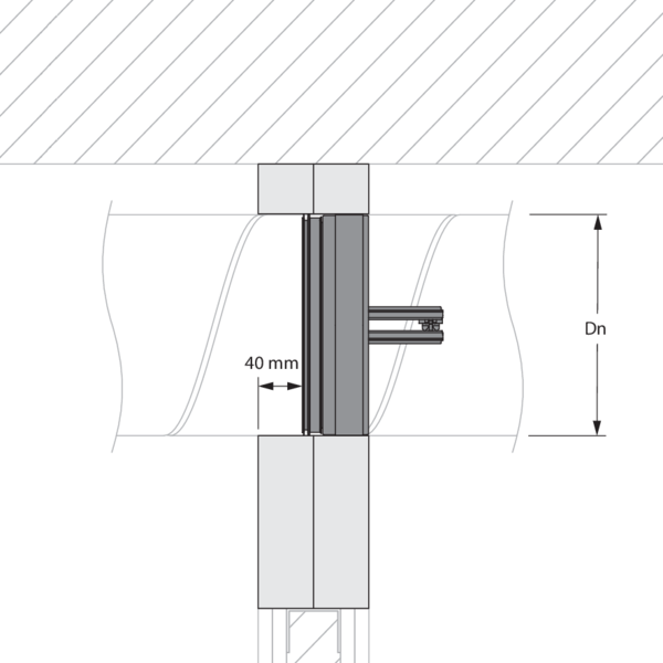
The duct in which the damper is inserted doesn't need be centered in the opening (with max dimensions duct + 600 mm). The maximal distance between the damper and the edge of the opening is 425 mm.
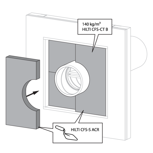
Installation in flexible wall, insulated duct, sealing with rigid stone wool boards with coating - SC+60
The product was tested and approved in:
- Metal studs gypsum plasterboard Type A (EN 520) ≥ 100 mm | EI 60 (ve i o) S - (300Pa) | Insulated duct (ArmaFlex EVO, ArmaFlex Protect – up to 13 mm) + stone wool + coating ≥ 140 kg/m³ | Type of installation: built-in inside a duct, 0-360° | SC+60 Ø 100-200 mm
The fire batt type Hilti CFS-CT B may be replaced by a similar type of fire batt with at least the same fire reaction class, density and thickness (tested according to EN 1366-3), for example PROMASTOP-CB 50 (CC).
The opening in the wall around the insulated duct, is sealed with 2 rigid stone wool boards of 50 mm with fire-resistant coating on one side (type PROMASTOP-CB50 / Hilti CFS-CT B).
The joints on these 2 layers must be installed staggered and covered all around the edge with coating (type PROMASTOP-CC / HILTI CFS-S-ACR).
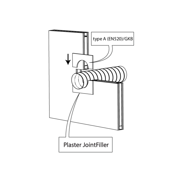
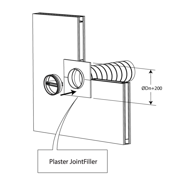
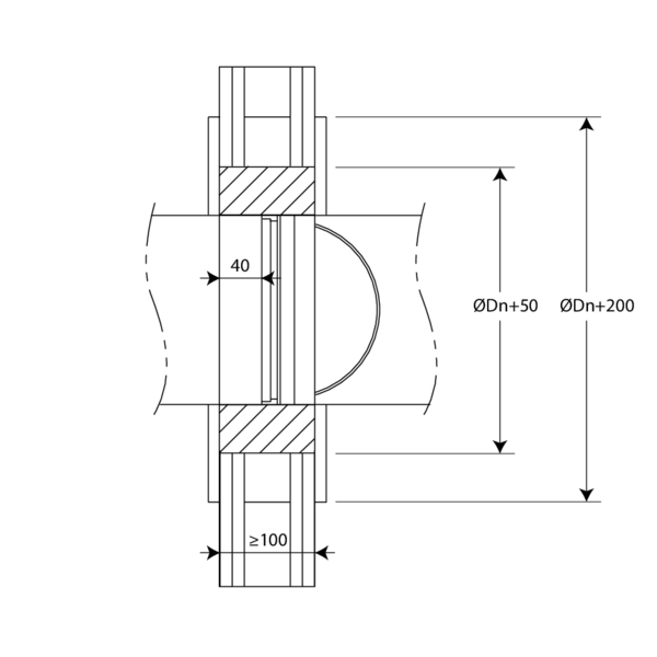
Installation in flexible wall with gypsum sealing - SC+60
The product was tested and approved in:
- Metal studs gypsum plasterboard Type A (EN 520) ≥ 100 mm | EI 60 (ve i o) S - (300Pa) | Gypsum | Type of installation: built-in inside a duct, 0-360°. Minimal distances authorised. | SC+60 Ø 100-200 mm
_INST_FW_GIPS_2.png)
_INST_FW_GIPS_3.png)
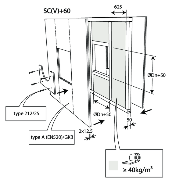
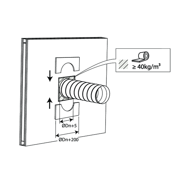
Installation in flexible wall, sealing with stone wool and cover plates - SC+60
The product was tested and approved in:
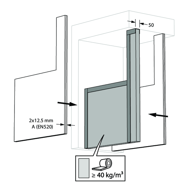
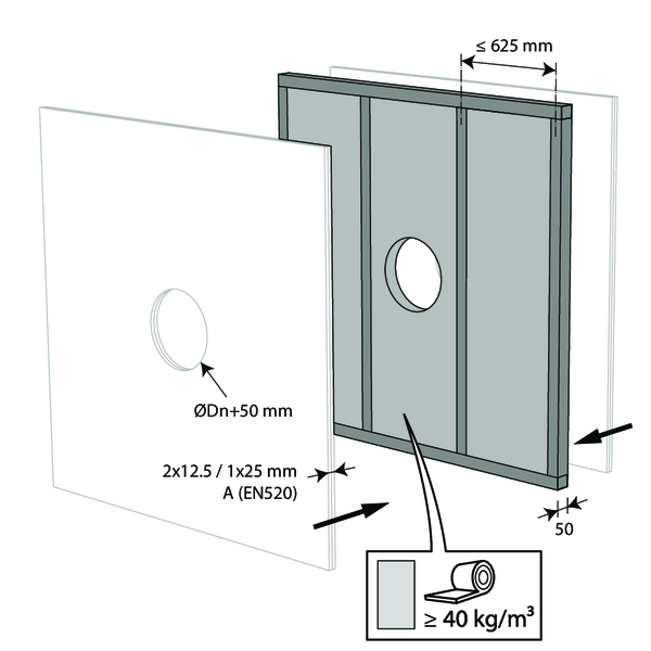
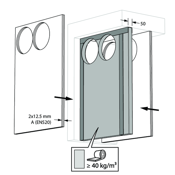
- Metal studs gypsum plasterboard Type A (EN 520) ≥ 100 mm | EI 60 (ve i o) S - (300Pa) | Stone wool ≥ 40 kg/m³ + cover plates | Type of installation: built-in inside a duct, 0-360° | SC+60 Ø 100-200 mm
Installation in flexible shaftwall, insulated duct, sealing with coated batt - SC+60
The product was tested and approved in:
- Metal studs gypsum plasterboard Type F (EN 520) ≥ 80 mm | EI 60 (ve i o) S - (300Pa) | Insulated duct (ArmaFlex EVO, ArmaFlex Protect – up to 13 mm) + stone wool + coating ≥ 140 kg/m³ | Type of installation: built-in inside a duct, 0-360° | SC+60 Ø 100-200 mm
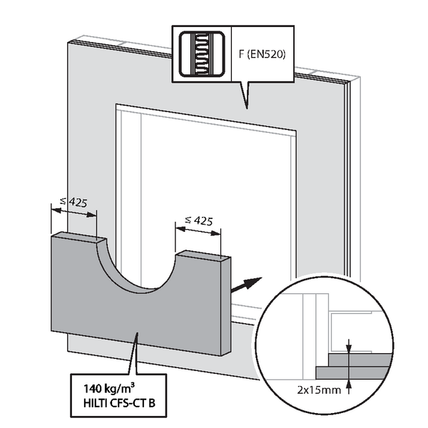
The fire batt type Hilti CFS-CT B may be replaced by a similar type of fire batt with at least the same fire reaction class, density and thickness (tested according to EN 1366-3).
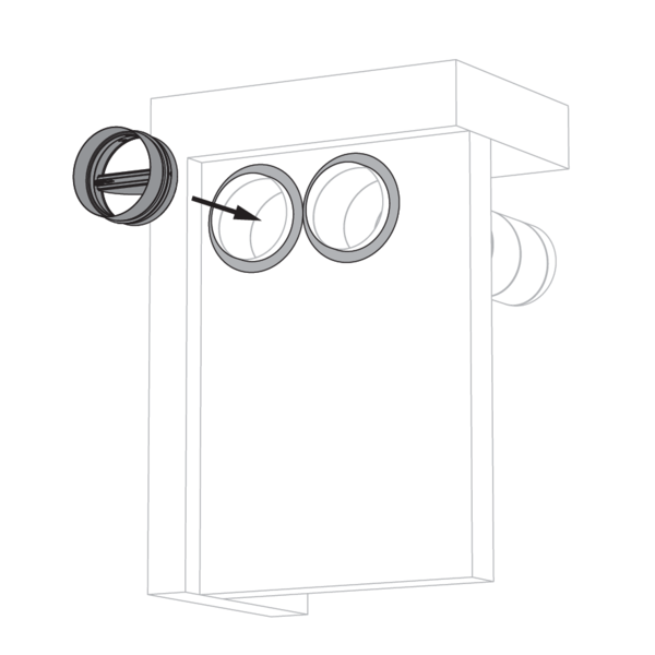
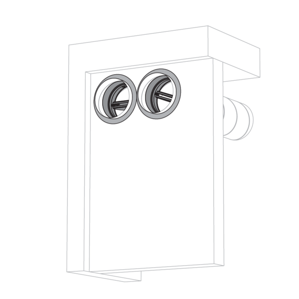
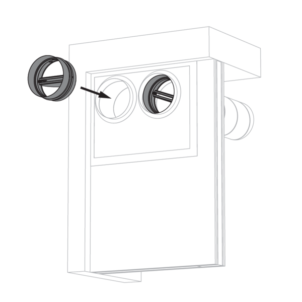
Place the fire damper cartridge with the fusible link/valve blades towards the shaft.
The opening in the wall around the insulated duct, is sealed with 2 rigid stone wool boards of 50 mm with fire-resistant coating on one side (type Hilti CFS-CT B).
The joints on these 2 layers must be installed staggered and covered all around the edge with coating (type HILTI CFS-S-ACR).
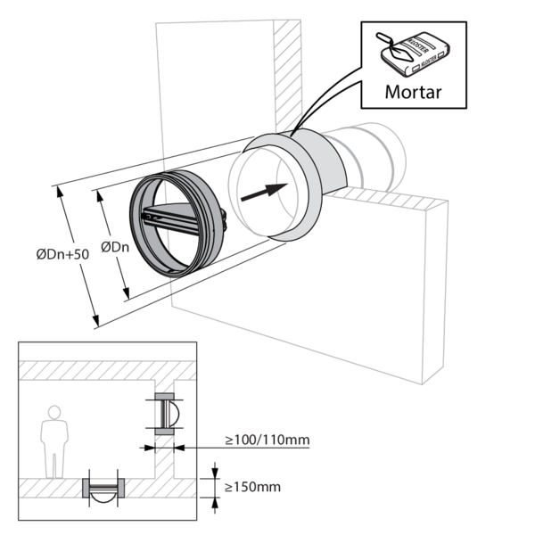
Installation in rigid wall and floor with mortar sealing - SC+60, SC+90 and SC+120
The product was tested and approved in:
- Aerated concrete ≥ 150 mm | EI 60 (ho i o) S - (300Pa) | Mortar | Type of installation: built-in inside a duct, 0-360° | SC+60 Ø 100-200 mm
- Aerated concrete ≥ 100 mm | EI 60 (ve i o) S - (300Pa) | Mortar | Type of installation: built-in inside a duct, 0-360° | SC+60 Ø 100-200 mm
General remarks
- Verify if the blade can move freely.
- The fire damper cartridge must remain accessible for inspection and maintenance.
- Please observe safety distances with respect to other construction elements.
Product-specific remarks
- The installation must comply with the installation manual and the classification report.
- The results obtained in standardised supporting structures according to EN 1366-2 also apply to similar supporting structures with a fire resistance, thickness and density equal to or greater than the supporting structure of the test. More information on standardised supporting structures: https://www.rft.eu/en-eu/page/fire-safety/legal-context/european-regulations/standardised-constructions
- Mounting direction: mounting possible with the axis in any position (0-360°)
- Direction of the airflow: discretionary
- If the product is manipulated in any other way than described in this manual, Rf-Technologies will decline any responsibility and the guarantee will expire!